Through channel loss prevention at a WDM node

Active Publication Date: 2006-05-18
CISCO TECH INC
View PDF11 Cites 21 Cited by
  • Summary
  • Abstract
  • Description
  • Claims
  • Application Information

AI Technical Summary

Problems solved by technology

The add/drop multiplexer has an input terminal which receives WDM signals from the optical fiber; an output terminal which transmits WDM signals to the optical fiber; at least one drop terminal for selected drop channels of WDM signals from the optical fiber; at least one add terminal for selected add channel

Method used


Image

  • Through channel loss prevention at a WDM node
  • Through channel loss prevention at a WDM node
  • Through channel loss prevention at a WDM node

Examples


Embodiment Construction

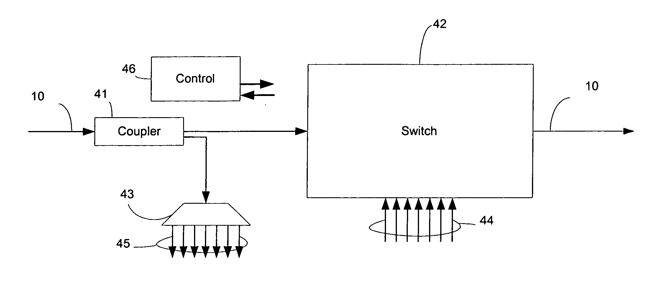
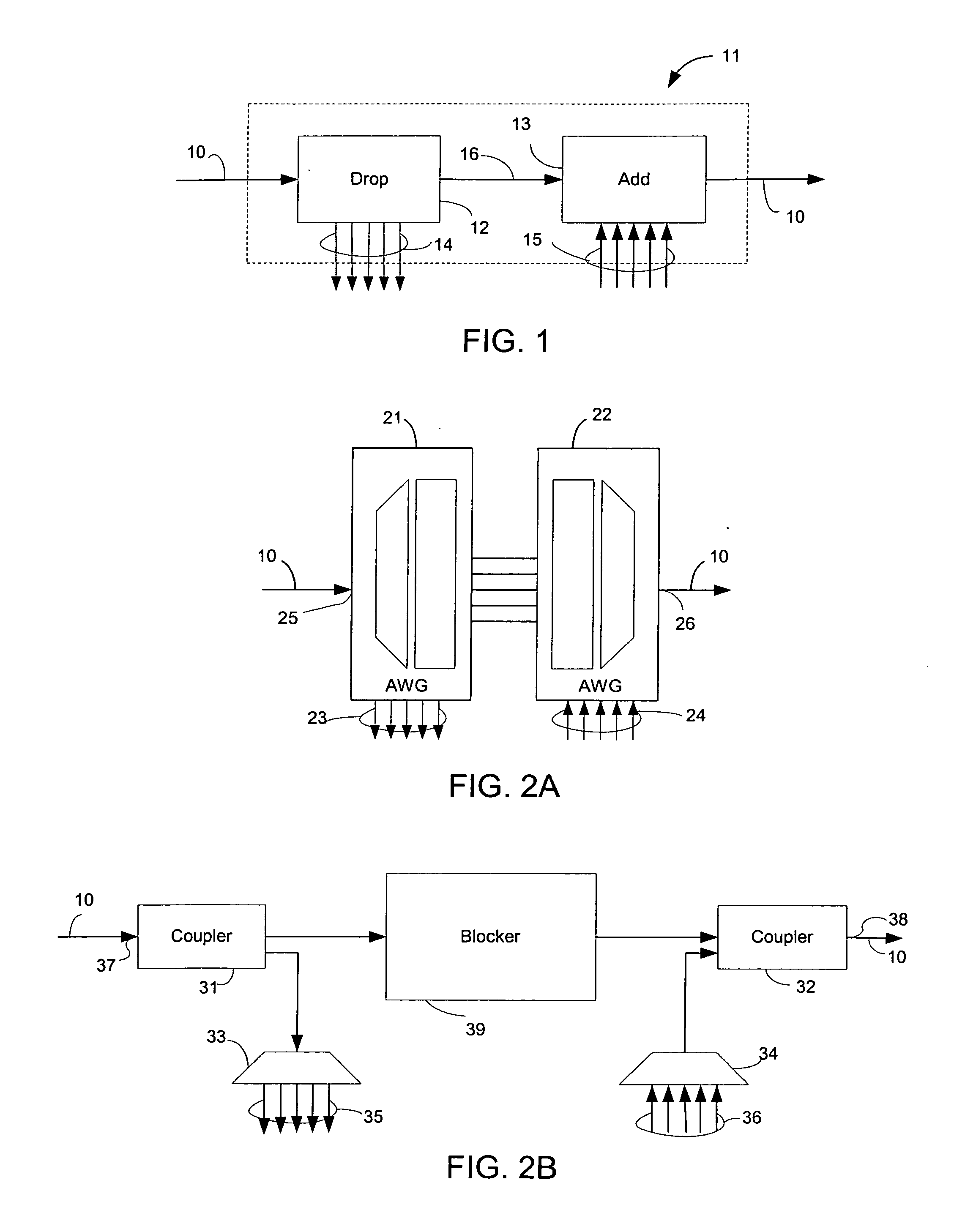
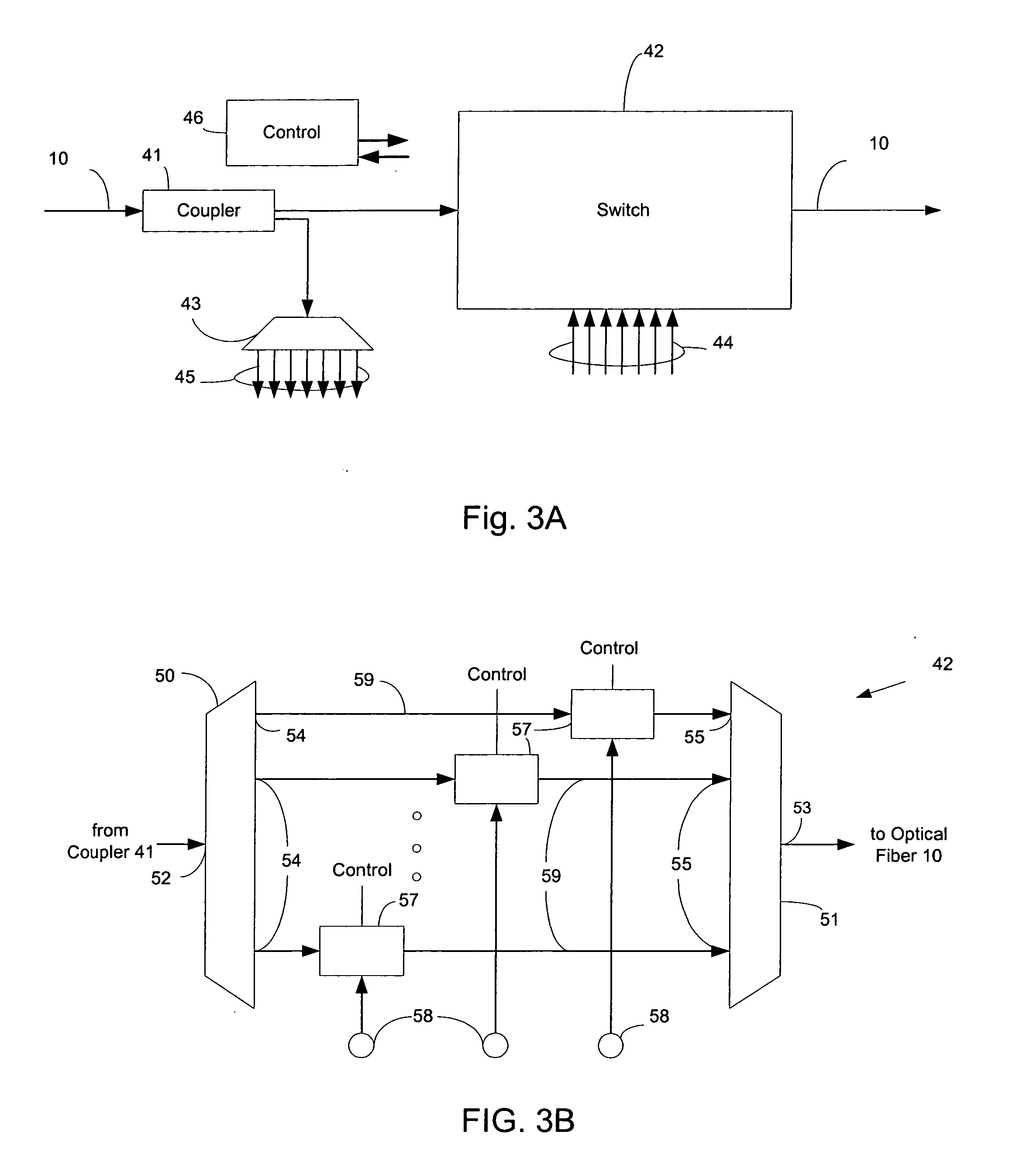
[0013]FIG. 1 is a general representative drawing of an add / drop multiplexer 11 for an add / drop node on an optical fiber 10. It should be noted that the term, “multiplexer,” is used in optical communication systems to loosely cover devices and combination of devices at different levels of complexity and organization. For example, add / drop multiplexers which are the subject of the present invention often contain constituent elements which are also termed “multiplexers” (or demultiplexers). These multiplexer elements are often interferometric in fundamental nature, and internally may be Mach-Zehnder interferometers, Fabry-Perot interferometers, arrayed waveguide gratings, devices based on crystal-based Fourier filter technology, etc. For purposes of clear exposition, such constituent elements are called multiplexer elements below. Furthermore, only one optical fiber 10 is shown for the purposes of clarity. Typical optical networks, such as SONET / SDH networks, operate with two optical f...


PUM


Abstract

At a WDM add/drop node of an optical fiber, an add/drop multiplexer system with opto-electric components in the through channel path has an optical switch connected in parallel with an add/drop multiplexer. Upon a power loss to the add/drop multiplexer, the optical switch bypasses the add/drop multiplexer so that WDM channel signals pass through the WDM add/drop node without interference from the unpowered add/drop multiplexer. Loss of through channels at the node is prevented. Upon a return of power, the optical switch reroutes the WDM signals on the optical fiber to the add/drop multiplexer but after the add/drop multiplexer is fully operational.

Description

BACKGROUND OF THE INVENTION [0001] The present invention is related to in general WDM (Wavelength Division Multiplexing) optical network systems and, more particularly, to systems and methods for protecting the loss of through communication channels at an add / drop node in the event of a power failure. [0002] In WDM systems, multiple optical signals having different wavelengths share an optical fiber, each wavelength defining a particular communication channel. Hence WDM systems include any system using optical wavelengths to define channels, such as DWDM (Dense Wave Division Multiplexing). This technique of wavelength division multiplexing has many advantages in implementing optical communication systems, including increased capacity and the ability to use passive optical components to redirect a portion of the data flowing along the optical fiber for processing at an intermediate node. [0003] A representative WDM system may include multiple nodes connected to one another by optical...

Claims


Application Information

Patent Timeline
IPC IPC(8): H04J14/02
CPCH04J14/0204H04J14/0205H04J14/0212H04J14/0213H04J14/0221H04J14/0227H04J14/0283H04J14/0297H04J14/0238H04J14/0228
Inventor CASANOVA, MAURO RUDIGHIONI, LORENZOMARCHIO, ANDREA
Owner CISCO TECH INC
Why Eureka
Try Eureka