
Management system for computer support systems

a management system and computer support technology, applied in the field of data storage systems, can solve the problems of high cost of approach, dramatically underutilized, system user active intervention, etc., and achieve the effect of significant downtim

Inactive Publication Date: 2006-05-18
IBM CORP
View PDF10 Cites 24 Cited by
  • Summary
  • Abstract
  • Description
  • Claims
  • Application Information

AI Technical Summary

Benefits of technology

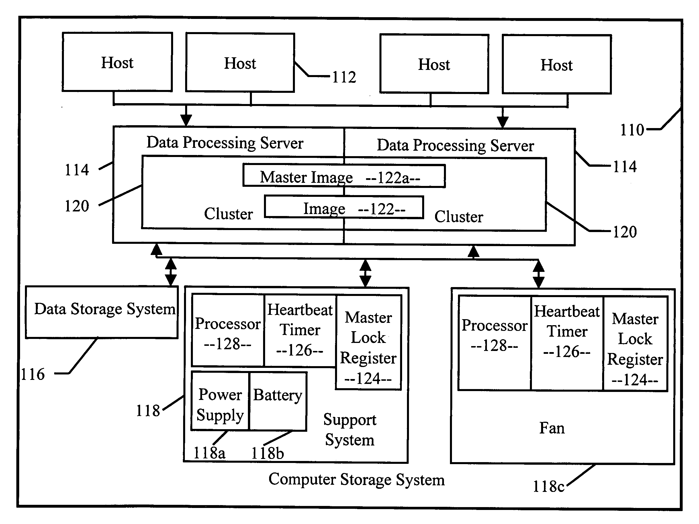
[0014] In order to ensure that the support system is actively managed, the master image must send a periodic message (“heartbeat”) to the support system. Any form of regular communication between the master image and the support system may serve as a heartbeat. Along with the master lock register, the support system includes a heartbeat timer and a digital processing device (“processor”). If the heartbeat timer expires due to lack of communication by the master image, the processor clears the master lock registers and transmits a broadcast message indicating that the support system needs a new master image. This broadcast message triggers each connected image to attempt to posses the master lock, just as they would do during initialization. This allows for ownership to dynamically pass from one image to another without image-to-image communication, system user intervention, failover profiles, and significant downtime between ownership.
[0015] The master lock may also be periodically polled by all images to check for ownership. This allows the support system to clear the master lock when it fails to receive a heartbeat message and precludes the need to transmit a broadcast message.

Problems solved by technology

However, this approach is extremely expensive as multiple devices are necessary and each may be dramatically underutilized.
However, a problem occurs if the image 22 tasked with managing the support systems 18 fails, precluding use of the support systems 18 by the other viable images.
However, this approach requires active intervention on the part of a system user.
However, no resources are provided for identifying which image is responsible for managing each hardware resource.
However, no provision has been made to ensure that a master image remains viable.
However, it is sometimes desirable to have independent systems on common hardware, precluding the use of image-to-image communication.

Method used


Image

  • Management system for computer support systems
  • Management system for computer support systems
  • Management system for computer support systems

Examples


Embodiment Construction

[0021] This invention is based on the idea of using a master lock register, a heartbeat timer, and a digital processing device to dynamically establish ownership of one or more support services in a computer system. The invention disclosed herein may be implemented as a method, apparatus or article of manufacture using standard programming or engineering techniques to produce software, firmware, hardware, or any combination thereof. The term “article of manufacture” as used herein refers to code or logic implemented in hardware or computer readable media such as optical storage devices, and volatile or non-volatile memory devices. Such hardware may include, but is not limited to, field programmable gate arrays (“FPGAs”), application-specific integrated circuits (“ASICs”), complex programmable logic devices (“CPLDs”), programmable logic arrays (“PLAs”), microprocessors, or other similar processing devices.

[0022] Referring to figures, wherein like parts are designated with the same r...


PUM


Abstract

A computer system includes a support system that report events, faults, and failures to a master virtual server. While the support system may be accessed and used by a multitude of virtual servers, only the master virtual server can manage the support system. The support system include a master lock register, a heartbeat timer, and a digital processing device (“processor”). Upon initialization and if the master lock register is empty, a virtual server asserts ownership over the support system by writing its identification into the master lock register, becoming the master virtual server. The master virtual server transmits periodic heartbeats to the support system to communicate that it is still viable and in control. If the heartbeat timer expires without communication from the master virtual server, the processor clears the master lock register and transmits a broadcast message inviting all connected virtual servers to attempt to assert control.

Description

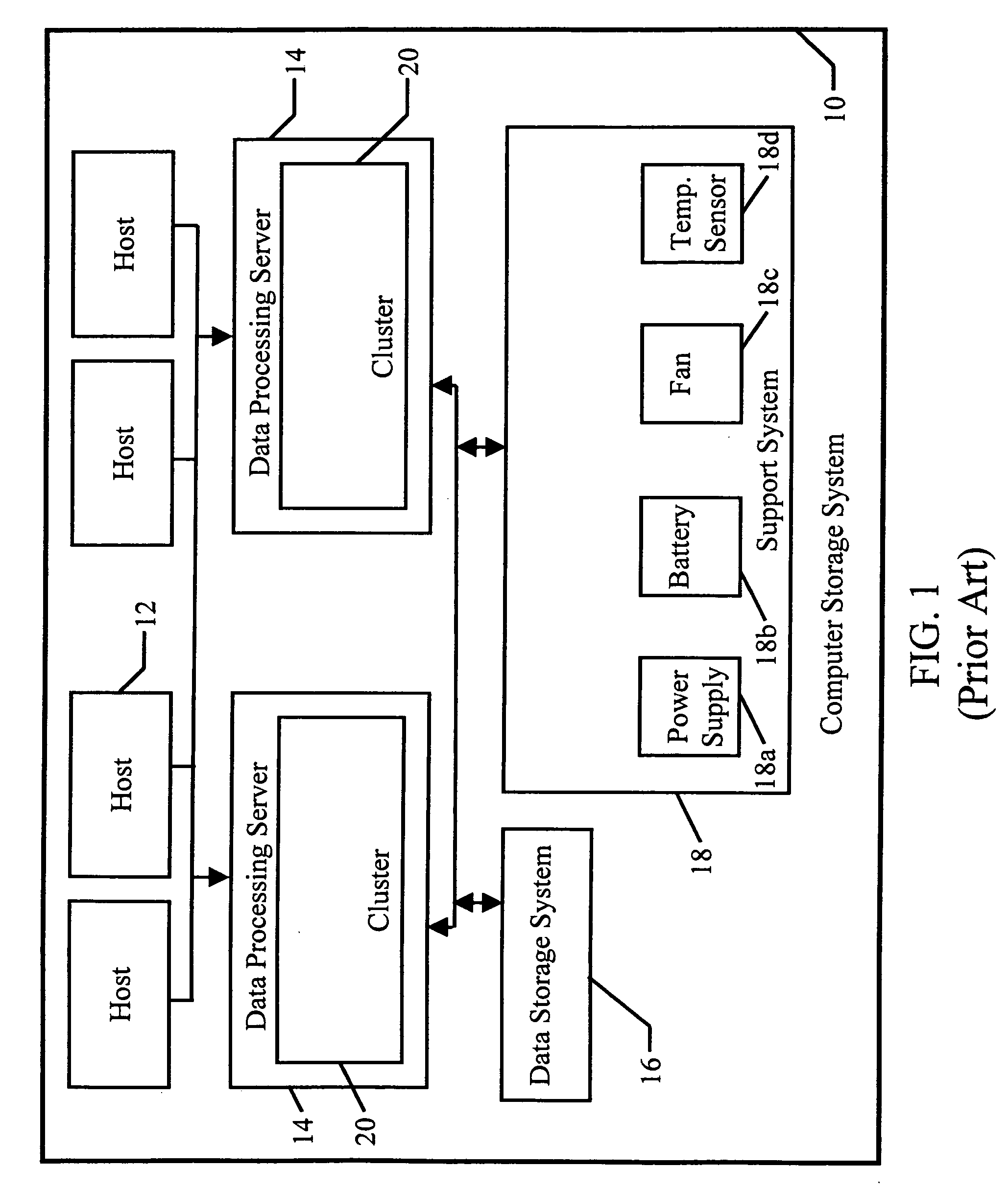
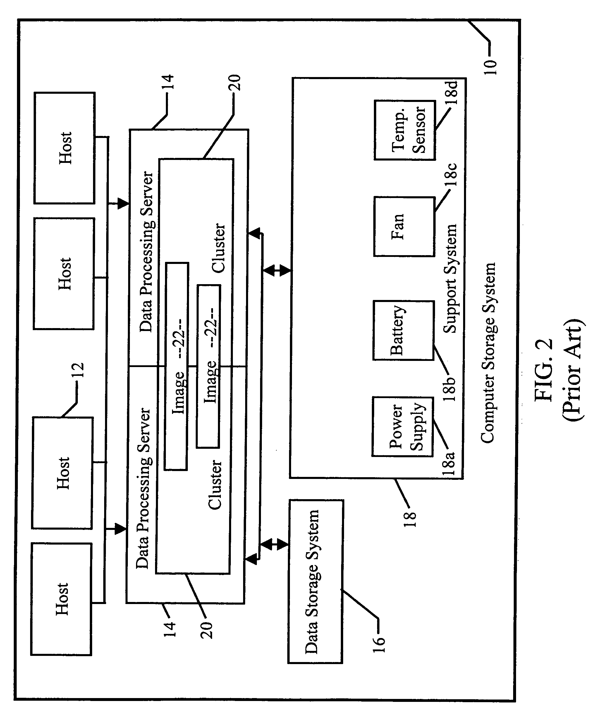
BACKGROUND OF THE INVENTION [0001] 1. Field of the Invention [0002] This invention is related in general to the field of data storage systems. In particular, the invention consists of a system for managing computer support systems. [0003] 2. Description of the Prior Art [0004] In FIG. 1, a computer storage system 10 includes host servers (“hosts”) 12, data processing servers 14, a data storage system 16, and various support systems 18 such as power supplies 18a, batteries 18b, fans 18c, and temperature sensors 18d. Each data processing server 14 may include a plurality of processing devices grouped into a processing cluster (“cluster”) 20 and may be substantially identical and redundant. Imposed upon the physical components of the computer storage system 10 may be a multitude of virtualized storage servers referred to as images 22 as shown in FIG. 2. Each image 22 typically resides on two or more clusters. In the event of a cluster failure, however, an image 22 can failover to the r...

Claims


Application Information

Patent Timeline
IPC IPC(8): H04N7/16
CPCG06F11/2033G06F11/1484G06F2201/815
Inventor CRAWFORD, TIMOTHY J.HUNT, BRANDON L.RINALDI, BRIAN A.RIPBERGER, RICHARD A.
Owner IBM CORP
Learn More