Device, system, and method for detecting equipment leaks

a technology of equipment and leakage detection, applied in the direction of instruments, fluid-tightness measurement, and measurement of fluid loss/gain rate, can solve the problems of increasing hydrogen consumption, reducing dielectric strength, and damaging stator phase to phase or ground fault, etc., to achieve accurate measurement of leakage rate, reduce downtime, and reduce equipment requirements. cost and large equipment requirements

Active Publication Date: 2021-03-16
REBICH NICK
View PDF2 Cites 1 Cited by
  • Summary
  • Abstract
  • Description
  • Claims
  • Application Information

AI Technical Summary

Benefits of technology

[0014]It is an object of the present invention to overcome the shortcomings of the traditional pressure and vacuum decay testing methods (time-consuming, costly, and large equipment requirements). For this reason, the present invention does not utilize the conventional pressure decay test methods. Instead, the present invention presents a novel device and method that incorporates principles of physics contained in Boyle's Law and Bernoulli's Principle coupled with laboratory and experimentally derived algorithms for measuring leak rates ranging from minute direct leak rates (typical of leaks within the water cooled stator / armature winding circuit resulting from component material porosity or chemical attack of the phosphorus rich copper braze alloy where small voids exist) to very large leak rates (typical of generator casing leaks). This is achieved by metering air flow via a precisely monitored and maintained source air pressure, custom made 45 degree conic edge orifice adapters (useful for even lower Reynolds numbers), and a specially manufactured high pressure Differential Pressure gauge. The present invention directly measures air flow through the leak under maintained test pressure and provides the positive pressure leak rate in SCFD in less than three hours (compared to the 24 hour or longer period used by current testing methods). The present invention may be used to accurately measure leak rates from as low as 0.053 SCFD to greater than 1200 SCFD in less than 3 hours.
[0015]The testing device, system, and procedure of the present invention can be used on any OEM liquid cooled generator stator armature winding and generator casing. It is recommended that OEM acceptance criteria and prescribed test pressures be followed. An improvement over traditional testing equipment and procedures, the testing equipment of the present invention is lightweight, portable, accurate, repeatable, and independent of test / generator volume and ambient conditions. Furthermore, while traditional equipment and techniques require substantial downtime for testing, the present invention requires less than 3 hours to provide results. Furthermore, the calculation software included with the testing system of the present invention allows for the immediate calculation of summarized results corrected to STP with a “pass or fail” flag for LCSW testing.
[0016]The following guidelines are believed to provide general examples of timing required for testing (but, of course, the testing procedure should be performed until the differential pressure maintains a steady reading for 20 minutes, as described more fully below with regard to the testing procedure of the present invention): (a) for volumes of less than 1 cubic foot, it is believed that stabilization will occur in less than 30 minutes, (b) for volumes greater than 1 cubic foot but less than 5 cubic feet, it is believed that stabilization will occur in less than 40 to 60 minutes, and (c) for volumes greater than 5 cubic feet, it is believed that stabilization will occur in less than 40 to 120 minutes. Given these guidelines, it is believed that the testing equipment and procedure of the present invention can save at least 24 hours over traditional testing equipment and methods. Thus, determining leak rates utilizing the present invention directly allows for the quick determination of work scope and logistics for repairs, ultimately reducing outage time and saving a substantial amount of money. As described more fully below with regard to the preferred testing procedure, the testing equipment of the present invention can be utilized after a gravity drain only (thus eliminating the need for the “blow down” stage and vacuum drying process required by traditional testing methods and equipment), saving an additional 24 to 48 hours. This improvement over the existing technology in this field is a result of the present inventions independence relative to the volume being tested. Furthermore, because the duration that the LCSW is under test pressure vs. blowdown pressures is substantially reduced, there is minimal risk of forcing moisture migration into the insulation system. Altogether, the technology of the present invention is an improvement over the traditional technology utilized to the tune of an estimated 48 to 72 hour time savings (in the scenario of a LCSW leak forced outage) and time savings in other applications as well.

Problems solved by technology

The second potential path for hydrogen leakage (thus resulting in an increase in hydrogen consumption) occurs within the liquid cooled armature winding circuit, which is housed within the generator casing and which commonly uses water or oil as a coolant.
If left uncorrected, moisture in the coil insulation will eventually lead to reduced dielectric strength of the insulation system resulting in a damaging stator phase to phase or ground fault.
This will result in the occurrence of a generator trip or shutdown, which may be referred to as an “emergency forced outage.”
Loss of a major power producing generator due to an emergency forced outage can be very costly (some estimate about $1000 per MW per day in losses) and can also jeopardize the stability of the transmission and distribution grid, ultimately resulting in power outages on the system.
It should be noted, however, that not all leaks can be detected by performing only one of the vacuum decay and pressure decay testing.
Unfortunately, as indicated above, these testing procedures are very technical, and because in LCSW scenarios both tests must be performed, a significant amount of equipment, set-up time, and testing time is required.
Furthermore, these tests are quite subjective and often not repeatable due to the fact that over the long testing period environmental factors (such as air temperature and barometric pressure) are changing.
All of these factors can have a significant impact on reducing the accuracy of leak rate calculations, and a new system, device, and method of testing for leaks in these types of equipment is needed.

Method used


Image

  • Device, system, and method for detecting equipment leaks
  • Device, system, and method for detecting equipment leaks
  • Device, system, and method for detecting equipment leaks

Examples


Embodiment Construction

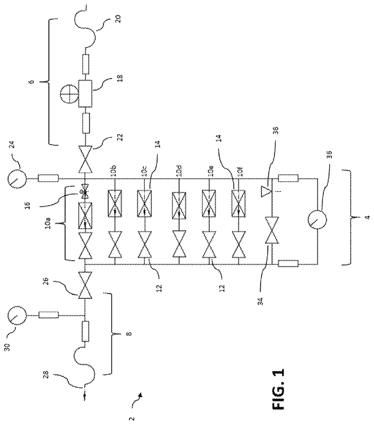
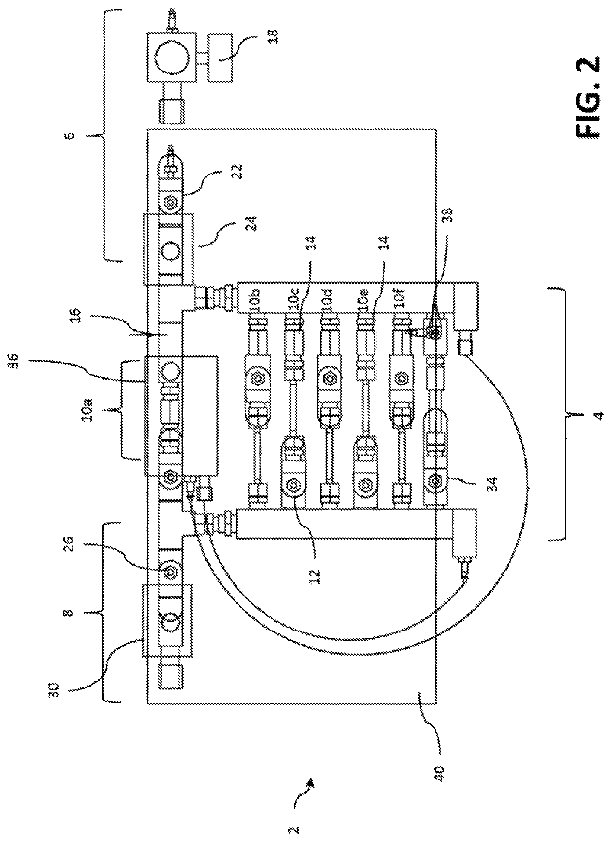
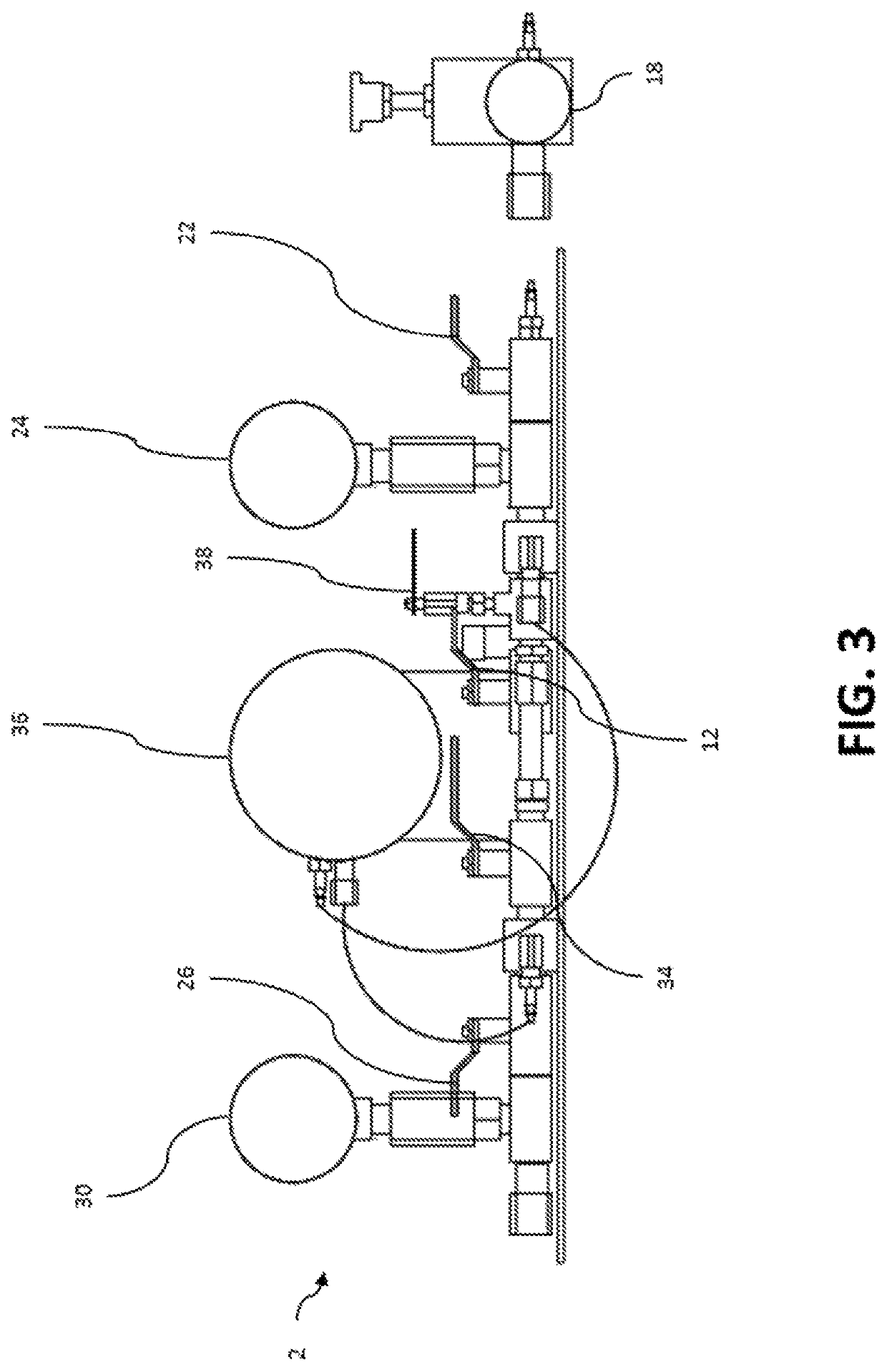
[0022]Generally speaking, the present invention is directed to a device, system, and method useful for accurately and expeditiously testing leak rates in hydrogen and liquid cooled electrical generator stator casings and armature windings of large industrial equipment, particularly steam turbine generators of all makes and sizes. In particular, the present invention is useful for and intended to be used for testing and quantifying leak rates in both liquid cooled generator stator windings (LCSW) and hydrogen cooled generator stator casings of steam turbine generators. The present invention utilizes Boyle's Law and Bernoulli's Principle coupled with laboratory and experimentally derived algorithms for measuring very minute leak rates using a specially manufactured high pressure differential pressure gauge and specially manufactured orifices for variable leak rates provided in stages. The algorithms are preferably incorporated into a computer-based form (such as an EXCEL spreadsheet) ...


PUM


Abstract

A device, system, and method for detecting a leak (and determining the leak rate of the leak) for equipment, particularly generators, the device including a main body connected to the tested equipment and to an air supply source, wherein the main body includes a number of stages each having a valve and orifice such that flow of air through the independent stages is selectively controllable, where a change in the differential pressure recorded during flow of the air through a particular stage indicates a leak, and wherein the differential pressure recorded can be used to calculate the rate of leak in the equipment.

Description

CROSS-REFERENCE TO RELATED APPLICATIONS[0001]This application claims priority from U.S. provisional patent application No. 62 / 666,332, filed on May 3, 2018, and entitled “Accurate Leak Rate Tester Device, System, and Method.” Such application is incorporated by reference herein in its entirety.STATEMENT REGARDING FEDERALLY SPONSORED RESEARCH OR DEVELOPMENT[0002]Not applicable.BACKGROUND OF THE INVENTION[0003]Dedicated, utility owned electrical power generating stations are the major sources of large amounts (Mega Watts and MVARs) of electrical energy required to provide the world's industrial, commercial and residential networks with reliable and stable electrical power. Many of these large power producing generators are designed to operate using pure hydrogen as a cooling media within the generator stator casing. In many cases the “larger” of the machines also utilize low conductivity water to provide direct cooling of the copper conductors via small passages within the strands tha...

Claims


Application Information

Patent Timeline
Patent Type & Authority Patents(United States)
IPC IPC(8): G01M3/28G01M3/36G01M3/00F17D5/02
CPCG01M3/28F17D5/02G01M3/007G01M3/366G01M3/3263
Inventor REBICH, NICK
Owner REBICH NICK
Why Eureka
Try Eureka