Small scale hybrid engine

a hybrid engine and small engine technology, applied in the direction of combustion engines, steam engine plants, hot gas positive displacement engine plants, etc., can solve the problems of penalizing the adoption of modified engines, affecting the performance of the actual power, and serious ignition problems of operating gasoline engines, etc., to achieve rapid conversion into pressure, high heat transfer rate, and large mass flow rate of intake air

Inactive Publication Date: 2006-05-25
FILIPPONE CLAUDIO
View PDF38 Cites 18 Cited by
  • Summary
  • Abstract
  • Description
  • Claims
  • Application Information

AI Technical Summary

Problems solved by technology

Most of these diesel operated gasoline engines have serious ignition difficulties, especially at sub-zero temperatures, and generally show poor performance with respect to the actual power available for energy extraction from the fuel.
Furthermore, increased fuel consumption with production of heavy smoke and pollutant emissions, and several other negative factors, severely penalizes the adoption of these modified engines.
Components like miniaturized compressor and exhaust gases wheels impose high degrees of manufactory accuracy and complexity.

Method used


Image

  • Small scale hybrid engine
  • Small scale hybrid engine
  • Small scale hybrid engine

Examples


Embodiment Construction

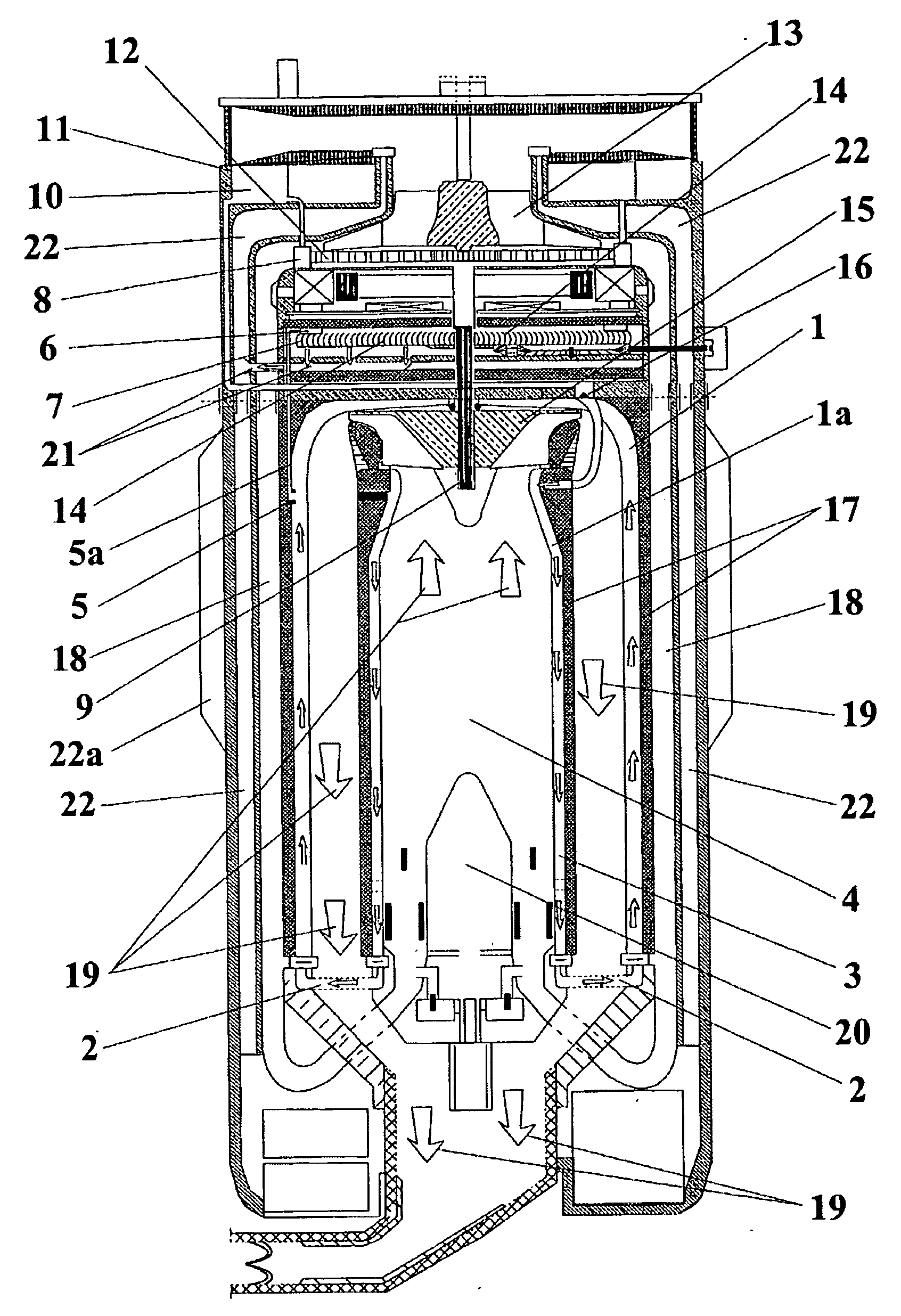
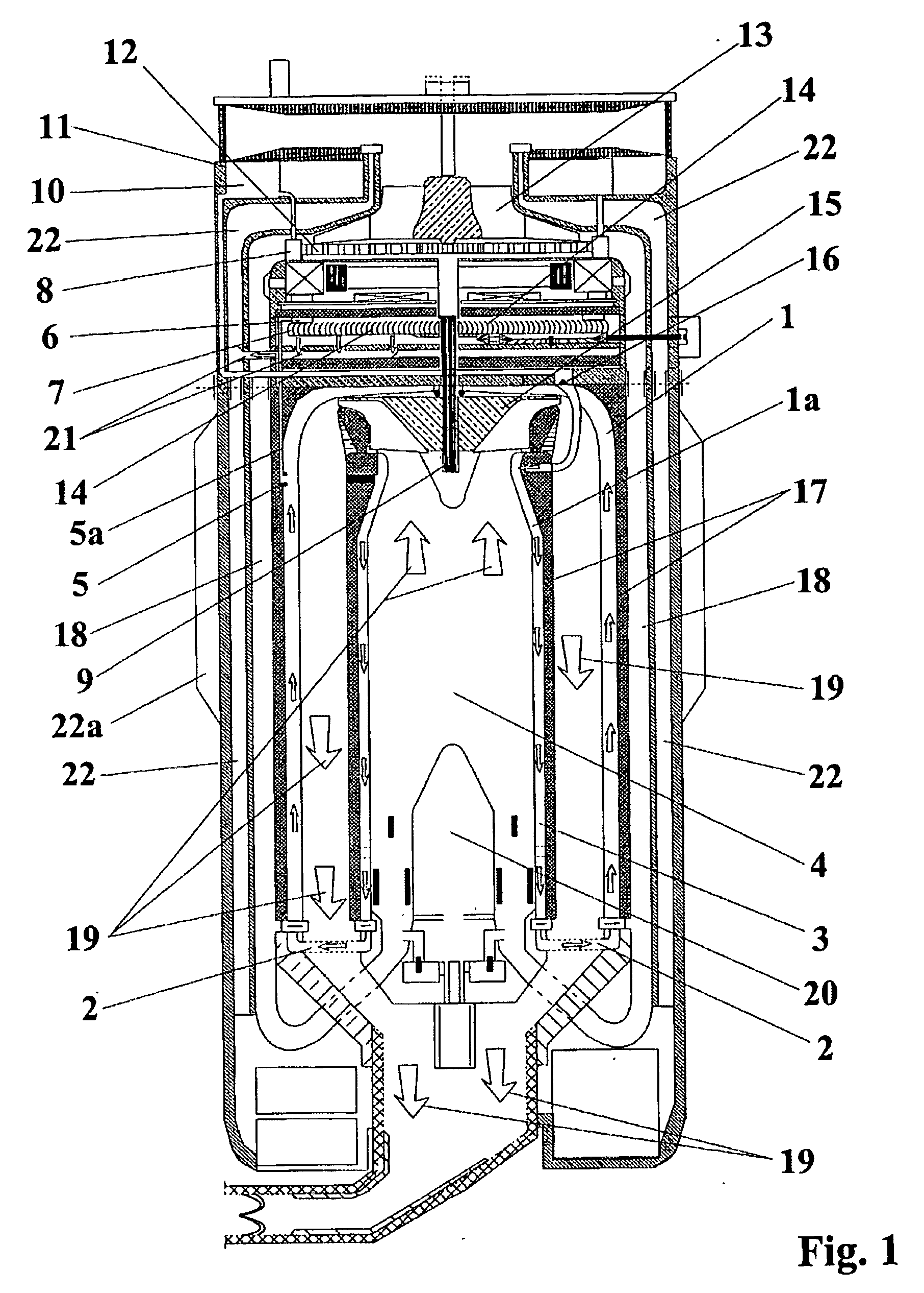
[0013] The working principles of the SSHE system are now described by utilizing the schematics and representations shown in FIGS. 1-7.

[0014] In FIG. 1, two cylindrical fluid expanding cavities 1, and la, here shown in cross-section view, are assembled around the basic structure of the SSHE combustion chamber 4. The body of the fluid-expanding cavity la is formed by concentric and sealed cylinders-like structures separated by a gap within which the working fluid 10 contained inside a toroidal storage tank 11 expands. Tank 11 shown in FIG. 1 is not to scale. Similarly, the body of fluid-expanding cavity 1 is formed by concentric sealed cylinders internally separated by a gap within which the working fluid 10 expands. Said working fluid 10 is pumped at relatively high-pressure inside the fluid expanding cavity 1a through one or more high-pressure miniaturized pump(s) 8 geared through a gear assembly 12 to a set of turbines 13, 14, and 15 linked to the same shaft 9. The high-pressure p...


PUM


Abstract

This invention describes a miniaturized hybrid diesel-electric engine formed by a closed-loop system powered by plasma-aided combustion of JP-8 fuel (or other hydrocarbon fuels) working in tandem with a vapor cycle utilizing miniaturized expanders and condensers. The output of this engine is electric power and mechanical work. Water, or organic fluids, heated by the combustion product developed inside a special burner, undergoes an explosive, quasi-supersonic conversion to steam. This steam drives a high-speed turbine connected together with a gas turbine outputting shaft work. This work output is utilized to power internal subsystems, cool down the miniaturized condensers, and to produce torque and electric power. The dimensions of this miniaturized hybrid-engine are so compact that it can fit inside the battery compartment of most applications requiring high-density miniaturized power sources.

Description

[0001] This is a continuation of application Ser. No. 10 / 261,685, filed Oct. 2, 2002, which is incorporated herein by reference.BACKGROUND OF THE INVENTION [0002] The conversion of compact gasoline spark ignition engines to diesel or heavy-fuels operated engines for various applications requiring miniaturized power sources, including robotics and exoskeleton, and small scale propulsion system, forces a series of adaptation of the current off-the-shelf engines. These adaptations allow a conventional miniaturized gasoline engine to be fueled by heavy-fuels at the expense of significant inefficiencies. Most of these diesel operated gasoline engines have serious ignition difficulties, especially at sub-zero temperatures, and generally show poor performance with respect to the actual power available for energy extraction from the fuel. Furthermore, increased fuel consumption with production of heavy smoke and pollutant emissions, and several other negative factors, severely penalizes the...

Claims


Application Information

Patent Timeline
Patent Type & Authority Applications(United States)
IPC IPC(8): F01K27/00F02B3/06F02G1/04
CPCF02B3/06F02G1/04
Inventor FILIPPONE, CLAUDIO
Owner FILIPPONE CLAUDIO
Why Eureka
Try Eureka