Supercharge Your Innovation With Domain-Expert AI Agents!

Process and device for measuring flow parameters

a flow parameter and flow process technology, applied in the direction of instruments, liquid/fluent solid measurement, respirators, etc., can solve the problems of enlargement of dead space, inability to carry particles in gas flows, and inability to meet the needs of users, etc., to achieve reliable measurement of flow parameters, ensure sufficient accuracy, and have a small space

Inactive Publication Date: 2006-05-25
DRAGERWERK AG
View PDF3 Cites 24 Cited by
  • Summary
  • Abstract
  • Description
  • Claims
  • Application Information

AI Technical Summary

Benefits of technology

The present invention provides a simplified process and device for measuring flow parameters without enlarging the dead space, requiring little space and affecting the flow resistance only insignificantly. The process involves the arrangement of a means for flow-induced sound generation in the area of the flow to be measured, measurement of the frequency and / or level of the sound generated, and determination of the flow parameters by processing the measured acoustic signals. The flow-induced sound generation takes place in a way that allows for the measurement of flow parameters without the need for a direct connection between the measuring device and the evaluation unit. The device includes an acoustic process for measuring flow parameters in flowing gases by inducing sound waves through the flow. The sound waves are generated by the flow-induced sound generation means and measured by an acoustic pick-up. The frequency of the sound waves depends on the direction of flow and the velocity of flow. The device can be used in respirators to measure breathing gas flows. The process and device provide a reliable and accurate means for measuring flow parameters with minimal impact on the flow.

Problems solved by technology

Another drawback of this process is its sensitivity to particles being carried in gas flows as well as contamination by sputum.
Since it is an electric measurement method, supply lines to the measuring element proper are, moreover, always necessary, which may lead to disadvantages in clinical practice in terms of applicability and user friendliness.
One drawback of this process is likewise the usually inevitable enlargement of the dead space as well as the complicated electronic evaluating and supply system, which must be connected directly to the measuring element in this case as well.

Method used


Image

  • Process and device for measuring flow parameters
  • Process and device for measuring flow parameters
  • Process and device for measuring flow parameters

Examples


Embodiment Construction

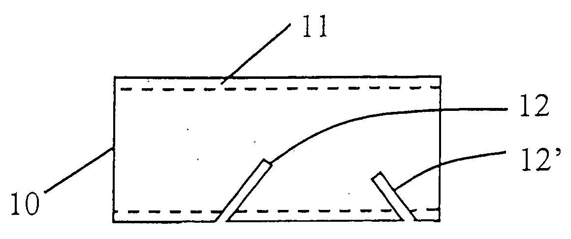
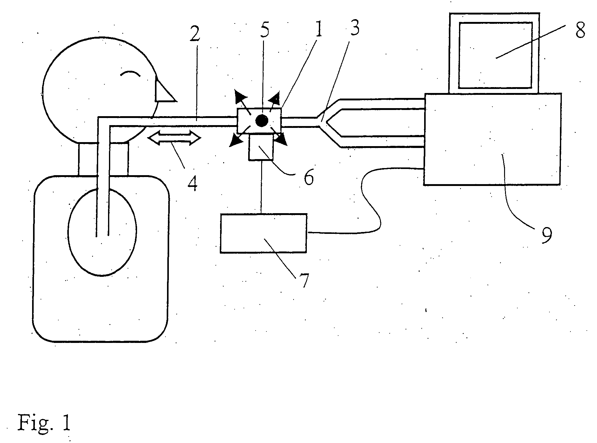
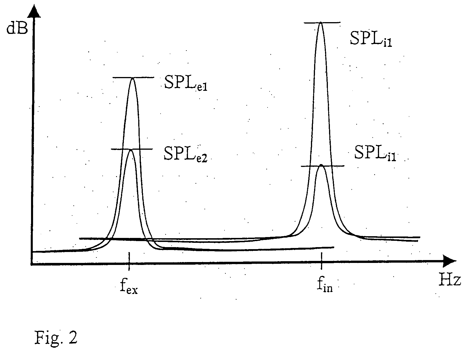
[0038] Referring to the drawings in particular, FIG. 1 shows a schematic arrangement for carrying out the process according to the present invention during the respiration of a patient. A flow sensor housing 1 is arranged between a tube 2 and a Y-piece 3. Flow with cyclic reversal of direction takes place up to the branching of the Y-piece 3. A source of sound 5 operated passively by respiration air is located in the flow sensor housing 1. During the respiration cycle, this source of sound generates acoustic signals, which can be received by a microphone probe 6, which is located outside the flow sensor housing 1. The source of sound 5 is constructed such that it generates a different acoustic frequency during inspiration than during expiration. The velocity and the volume flow that is flowing through the tube 2 can be determined from the spectrum of the acoustic signals, by means of a device for digital signal processing 7, and the velocity of flow can be inferred from the loudness...


PUM


Abstract

A process device and system for measuring flow parameters in flowing gases is provided in which a device for flow-induced sound generation is in the area of the flow to be measured. A measurement of the frequency and / or the level of the sounds generated is made during the flow to be measured as acoustic parameters. A determination is made as to the flow parameters to be measured by processing the measured acoustic parameters. The process makes possible, in particular, the measurement of the volume flows during respiration near the patient.

Description

CROSS REFERENCE TO RELATED APPLICATIONS [0001] This application claims the benefit of priority under 35 U.S.C. § 119 of German Application DE 10 2004 055 968.6 filed Nov. 19, 2004, the entire contents of which are incorporated herein by reference. FIELD OF THE INVENTION [0002] The present invention pertains to a process and a device for measuring flow parameters in flowing gases. It can be used wherever volume and mass flows are to be determined in flowing gases. BACKGROUND OF THE INVENTION [0003] To determine volume and mass flows in flowing gases, it is usual and meaningful to determine flow parameters at individual measuring points and to determine the overall flow from these measured values by extrapolation over time and / or space. Flow parameters are either measured for this purpose directly or derived from the measurement of other physical variables, which unambiguously depend on the flow parameters, by the use of various evaluation algorithms. The measurement method is selecte...

Claims


Application Information

Patent Timeline
Patent Type & Authority Applications(United States)
IPC IPC(8): G01F1/32
CPCA61M16/00A61M2016/0021A61M2016/0036A61M2205/3375G01F1/666G01P13/04A61M16/024
Inventor KUO, ARTUR CHUNG-CHEZIMMERMANN, STEFAN
Owner DRAGERWERK AG
Features
  • R&D
  • Intellectual Property
  • Life Sciences
  • Materials
  • Tech Scout
  • Unparalleled Data Quality
  • Higher Quality Content
  • 60% Fewer Hallucinations
Learn More