Sewing machine

a sewing machine and thread technology, applied in the field of sewing machines, can solve the problems of user being forced to lift the lifting lever of the presser foot, user being unexceptionally required to lift the presser foot, and user being unable to hook the thread on the thread tension, etc., to achieve the effect of improving operability

Active Publication Date: 2006-05-25
BROTHER KOGYO KK
View PDF5 Cites 7 Cited by
  • Summary
  • Abstract
  • Description
  • Claims
  • Application Information

AI Technical Summary

Benefits of technology

[0014] According to such construction, upon completion of embroidery sewing, the actuator is driven so that the covering member is moved to the opening position. That is, the movement of the covering member to the opening position is not performed in conjunction with the lifting operation of the presser foot lifting lever, but is performed automatically by the drive force of the actuator, upon completion of embroidery sewing. Therefore, the covering member can be moved to the opening position without having to take the steps of operating the presser foot lifting lever, and the thread exchange to be carried out upon sewing the subsequent embroidery patterns become easier, thereby improving the operability.

Problems solved by technology

Therefore, the user is unexceptionally required to lift the presser foot lifting lever upon hooking the needle thread on the thread tension regulator.
In this state, the user is not able to hook the thread on the thread tension regulator and the thread take-up.
Consequently, a large operational force is imposed upon the user, providing very poor operability.
This necessity results in problems such as an increase in the number of parts.

Method used


Image

  • Sewing machine
  • Sewing machine
  • Sewing machine

Examples


Embodiment Construction

[0034] One embodiment according to the present invention will be described hereinafter with reference to the drawings.

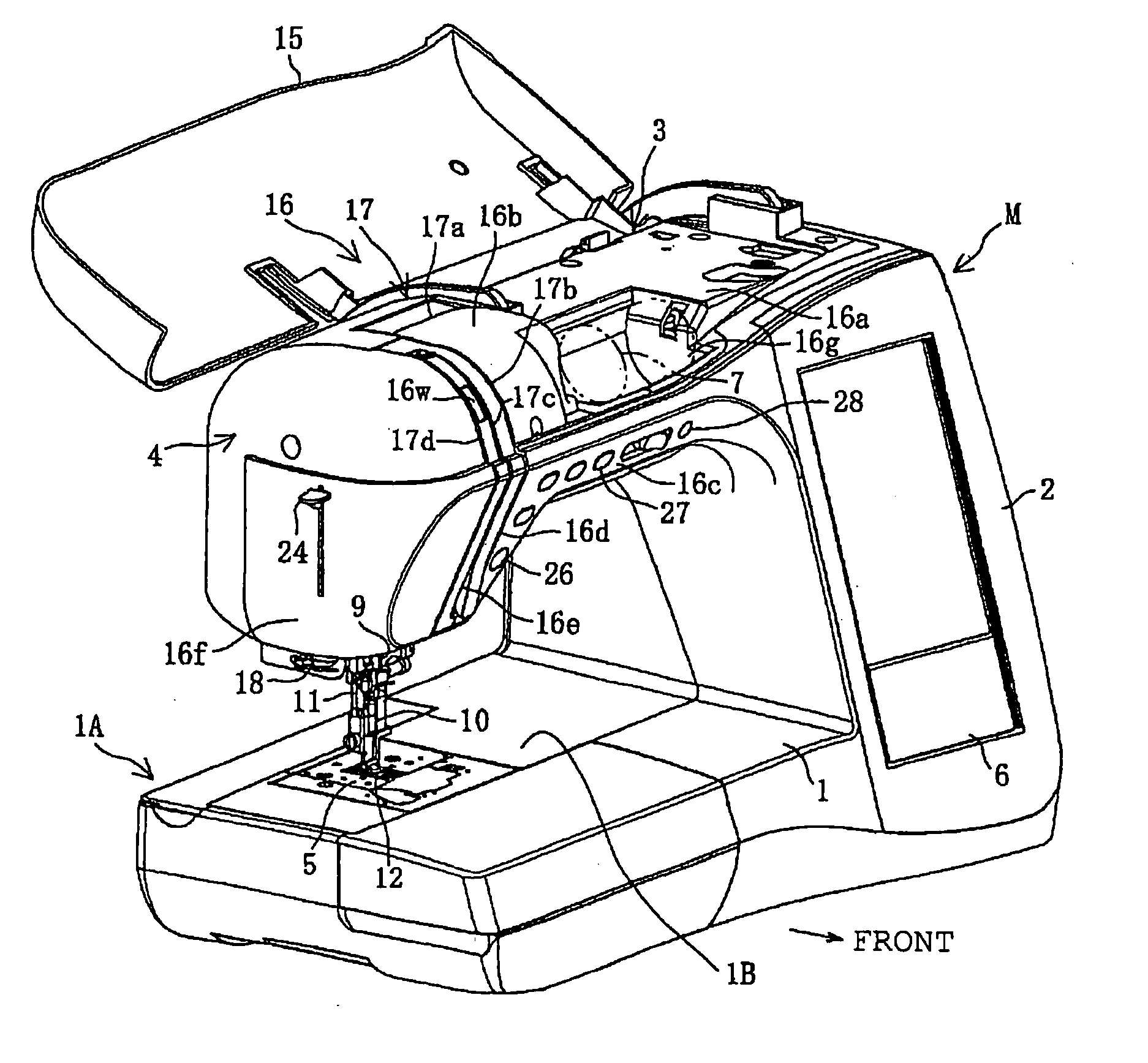
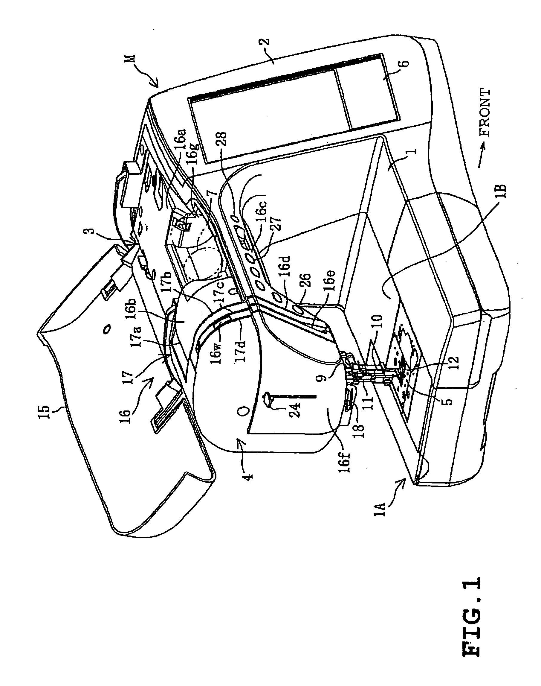
[0035] As shown in FIG. 1, the electronic sewing machine M includes a bed 1, a pillar 2 standing on the right end of the bed 1, an arm 3 extending leftward so as to oppose the bed 1, and a head 4 provided on the left end of the arm 3. A needle plate 5 is provided on the bed 1. A thread trimming mechanism 85 (refer to FIG. 13), a rotary hook (not shown), and the like are provided below the needle plate 5. To the rotary hook, a bobbin wound with a lower thread is detachably attached to the rotary hook. A large type vertical liquid crystal display 6 is provided on the front surface of the pillar 2. An arm cover 15 covering the arm 3 is provided on the arm 3. This arm cover 15 is rotatably supported by a rotational shaft laterally provided on the upper-rear end of the arm 3.

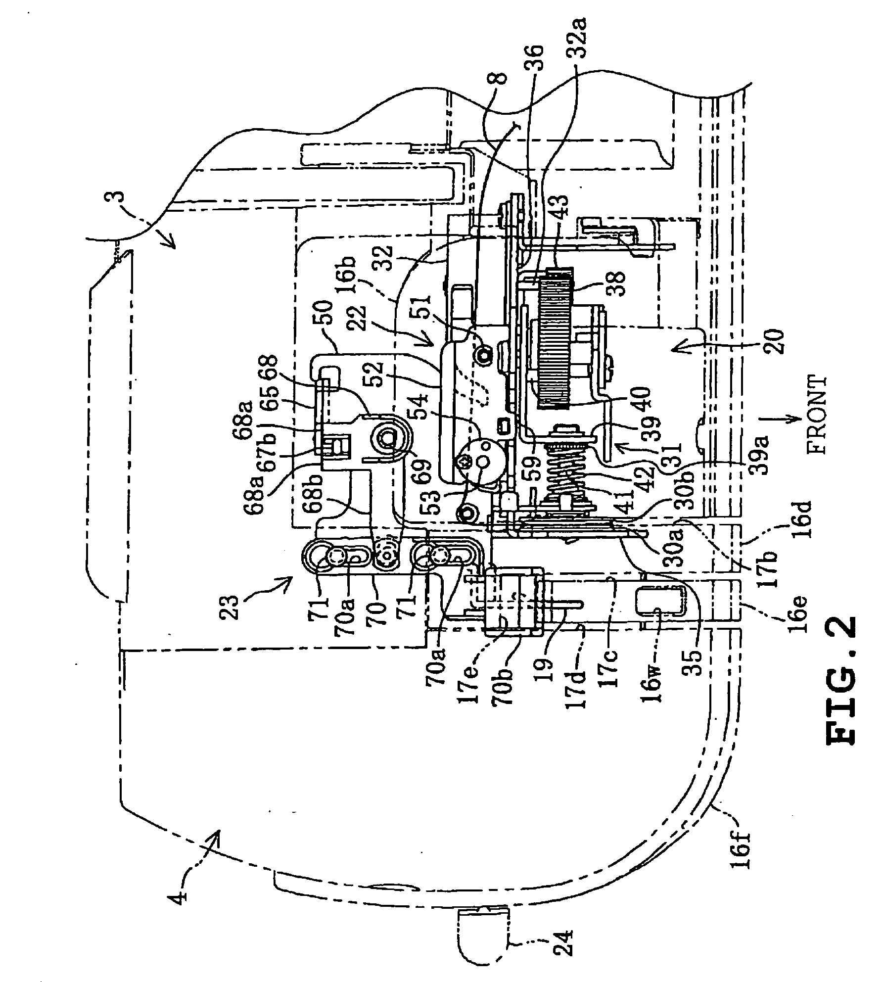
[0036] A sewing machine cover 16 is provided on the arm 3. The sewing machine cover 16, as shown...


PUM


Abstract

The sewing machine includes a presser foot that is lowered to press a workpiece cloth; a presser foot lifting lever operating the presser foot; a thread tension mechanism including a thread tension regulator capable of adjusting the thread tension of a needle thread and opening the thread tension regulator based on the lifting operation of the presser foot lifting lever; and a thread guide groove guiding the needle thread at least to the thread tension mechanism, upon carrying out the thread hooking work. The sewing machine further includes a detector detecting a lifting operation of the presser foot lifting lever; a covering member which is movable between a closed position where the covering member covers at least a part of the thread guide groove and an opened position where the covering member opens the thread guide groove. The covering member is moved to the closed position when the presser foot is in a lowered state. An actuator moves the covering member at least from the closed position to the opened position. A controller controls the actuator so that the covering member is moved to the opened position when the detector detects the lifting operation of the presser foot lifting lever.

Description

CROSS-REFERENCE TO RELATED APPLICATIONS [0001] This application is based upon and claims the benefit of priority from the prior Japanese Patent Application No. 2004-339074, filed on Nov. 24, 2004 the entire contents of which are incorporated herein by reference. BACKGROUND OF THE INVENTION [0002] 1. Field of the Invention [0003] The present invention relates to a sewing machine in which a needle thread drawn from a thread supply is hooked along a thread guide groove, and more particularly to such a sewing machine provided with means for preventing errors in hooking the thread to a thread tension regulator. [0004] 2. Description of the Related Art [0005] A sewing machine is provided with a thread tension mechanism that opens and closes a thread tension regulator constructed by a pair of thread tension discs. The thread tension mechanism is linked to a presser foot lifting lever. When a user lifts the presser foot lifting lever, the thread tension regulator is opened. In this state, t...

Claims


Application Information

Patent Timeline
Patent Type & Authority Applications(United States)
IPC IPC(8): D05B29/00
CPCD05B19/12D05B29/00D05B47/04D05B65/02D05B73/005
Inventor TERAO, AKIRANAKAGAWA, YOKOHIROSE, HIROKAZU
Owner BROTHER KOGYO KK
Why Eureka
Try Eureka