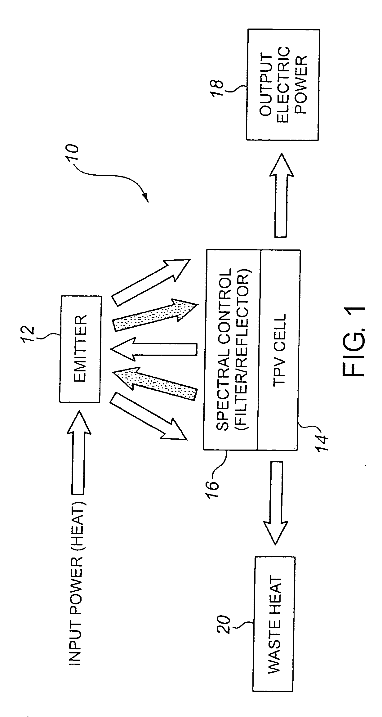
Thermophotovoltaic device
a technology of thermophotovoltaic cells and thermophotovoltaic cells, which is applied in the direction of photovoltaic devices, electrical devices, and semiconductor devices, can solve the problems of increasing cell temperature, affecting the efficiency of thermophotovoltaic calls, and the inability to use long wavelength energy by the photovoltaic cells, etc., to achieve the effect of preventing heat transfer to the thermophotovoltaic cells, reducing cell temperature and low conductivity
- Summary
- Abstract
- Description
- Claims
- Application Information
AI Technical Summary
Benefits of technology
Problems solved by technology
Method used
Image

Examples
example i
With Dielectric Filters Without Quartz Tubes Installed
[0068] Data taken after system was fired at 12 kW for 50 minutes.
[0069] Middle hole burner temperature—937° C.
[0070] Bottom hole burner temperature—1006° C.
[0071] Average Temperature—971.5° C.
[0072] Total Black Body Power 5.67×10−8×(971.5+273.15)4=13.6 W / cm2
With Quartz Tube Filters Installed
[0073] Data taken after system was fired at 12 kW for 50 minutes.
[0074] Middle hole burner temperature—1001° C.
[0075] Bottom hole burner temperature—1069° C.
[0076] Average Temperature=1035° C.
[0077] Total Black Body Power=5.67×10−8×(1035+273.5)4=16.6 W / cm2
Average Power Increase Due to Quartz Tubes=16.6−13.6 / 13.6×100%=22%
example 2
[0078] Without Dielectric Filters Without Quartz Tubes Installed
[0079] Data taken after system was fired at 12 kW for 1 hr.
[0080] Burner—temp in inferred from current vs. temperature plot—71° C. (middle hole)
[0081] Total Black Body Power=5.67×10−8×(710÷273.1 5)4=5.3 W / cm2
With Quartz Tube Filters Installed
[0082] Data taken after system was fired at 12 kW for 1 hr.
[0083] Burner temp interred from current vs. temperature plot—800° C. (middle hole)
[0084] Total Black Body Power=5.67×10−8×(800+273.15)4=7.5 W / cm2
[0085] Average Power increase due to quartz tubes=7.5−5.3 / 5.3×100%=42%
PUM
 Abstract
Description
Claims
Application Information
 - R&D
- Intellectual Property
- Life Sciences
- Materials
- Tech Scout
- Unparalleled Data Quality
- Higher Quality Content
- 60% Fewer Hallucinations
Browse by: Latest US Patents, China's latest patents, Technical Efficacy Thesaurus, Application Domain, Technology Topic, Popular Technical Reports.
© 2025 PatSnap. All rights reserved.Legal|Privacy policy|Modern Slavery Act Transparency Statement|Sitemap|About US| Contact US: help@patsnap.com