Optical fiber cable take-up mechanism for scanning sensors

Active Publication Date: 2006-05-25
HONEYWELL INT INC
View PDF31 Cites 28 Cited by
  • Summary
  • Abstract
  • Description
  • Claims
  • Application Information

AI Technical Summary

Benefits of technology

[0007] The present invention is based in part on the recognition that various performance advantages can be achieved by developing a spectrometric, e.g., infrared, scanning system where the weight of the moving scanner or sensor head is minimized. In a preferred embodiment, this is ac

Problems solved by technology

In view of the spectral nature of the measurement and the mechanical properties of the optical fiber, disturbances to the orientation and/or configuration of the optical fiber can adversely affect the spectral content of light returning to the detector system.
This will perturb the measurements.
For example, changes to the net bent length of

Method used


Image

  • Optical fiber cable take-up mechanism for scanning sensors
  • Optical fiber cable take-up mechanism for scanning sensors
  • Optical fiber cable take-up mechanism for scanning sensors

Examples


Example

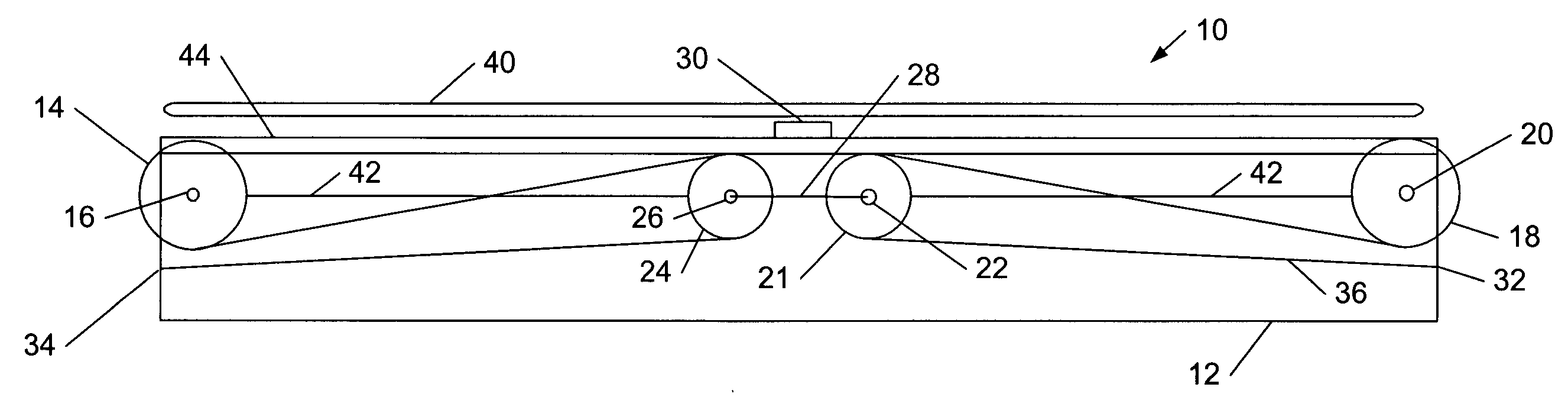
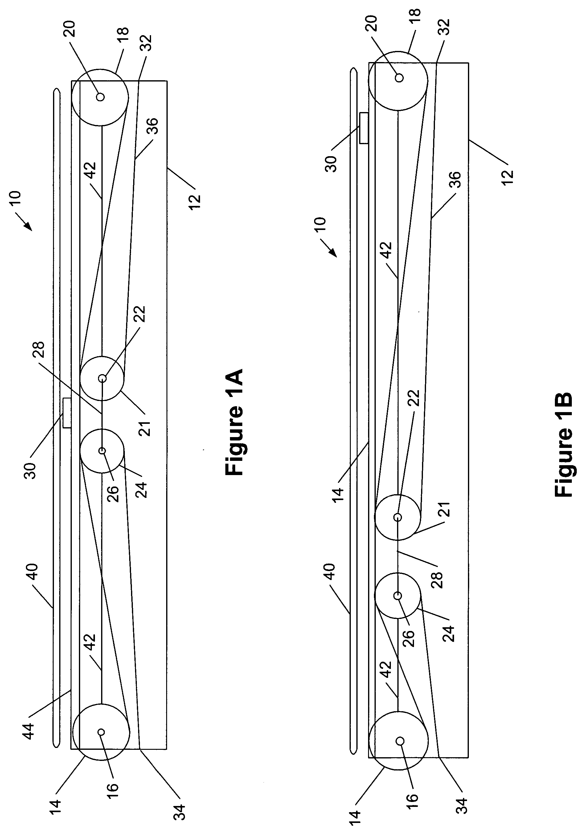
[0045]FIG. 1A illustrates an embodiment of the cable take-up mechanism 10 of the present invention which includes a frame 12 that is constructed of steel or other material(s) of sufficient structural strength. Typically, for scanning systems that are employed to scan in the cross direction of a moving sheet or web 40, the length of the frame 12 is about the same as the width of the moving sheet 40 so that the scanner head 30 is able to traverse the entire width along the cross direction. This distance can be six to eight meters or more. Located on one side of the frame 12 is a first fixed turning pulley 14 which is secured to the frame by pin 16. Positioned on the other side of the frame is second fixed turning pulley 18 which is secured by pin 20. The distance between pins 16 and 20 preferably range from 2 to 12 meters. The diameters of the two fixed turning pulleys 14, 18 are preferably the same. Each pulley preferably has a groove around its outer perimeter that is dimensioned to...


PUM


Abstract

A scanning system includes a cable take-up mechanism that uses a series of pulleys that determine the bend diameters of a scanning system. The mechanism is particularly suited for a spectrometric, e.g., infrared, scanning system where moving scanner or sensor head essentially houses only the optical elements while essentially of all the other electronic and optical components associated with the measurement are housed in an easily accessible compartment that is remote from the moving scanner head. Light is transmitted through optical fiber cables. The cable take-up mechanism maintains the fiber optic cable at essentially constant total bend length and bend diameter thereby minimizing any dynamic changes to spectral bend losses as the optical head is scanned. The light weight construction of the sensor head further reduces vibrations associated with the moving scanner head.

Description

FIELD OF THE INVENTION [0001] The present invention generally relates to an apparatus for routing moving flexible cables wherein the radius of curvature of the cable and the nominal total bend length is maintained and to a device that controls the optical fiber path through a series of bends that do not change in number or diameter even as the optical fiber is moved back and forth along a defined linear path. BACKGROUND OF THE INVENTION [0002] It is often desirable to obtain measurements of selected characteristics of sheet materials during manufacture. Although various properties of sheet materials can be detected by off-line laboratory testing, such tests often are not practical because of the time required for sample acquisition and analysis. Also, laboratory testing has the shortcoming that samples obtained for testing may not accurately represent sheet material that has been produced. [0003] To overcome the drawbacks of laboratory testing of sheet materials, various sensor syst...

Claims


Application Information

Patent Timeline
IPC IPC(8): H04N1/32
CPCG01N21/3554G01N21/8806G01N21/89G01N2201/103G01N21/3559
Inventor BESELT, RONALD E.HARAN, FRANK M.HARJULA, JOHN A.DOS SANTOS, ULYSSE S.
Owner HONEYWELL INT INC
Why Eureka
Try Eureka