Solar pumped laser microthruster

Inactive Publication Date: 2011-11-10
LAWRENCE LIVERMORE NAT SECURITY LLC
View PDF10 Cites 8 Cited by
  • Summary
  • Abstract
  • Description
  • Claims
  • Application Information

AI Technical Summary

Benefits of technology

[0012]The development of microsatellites requires the development of engines to modify their orbit or orientation. The present invention provides embodiments that use solar energy to drive such engines. For an unlimited energy source, the optimal thruster must use a minimal amount of expendable material minimize weight and therefore minimize launch costs. This requires the ejected material to have the maximal velocity and hence, the ejected atoms must be as light

Problems solved by technology

The weight of the engine and the weight of the required fuel are detrimental factors.
Problems presented by these systems include the high power consumption required to ionize accelerating atoms, the need to compensate the spacecraft charge and the system complexity.
Due to the incoherence of solar light, it is impossible to use it directly and to to get high-energy concentration an

Method used


Image

  • Solar pumped laser microthruster
  • Solar pumped laser microthruster

Examples


Example

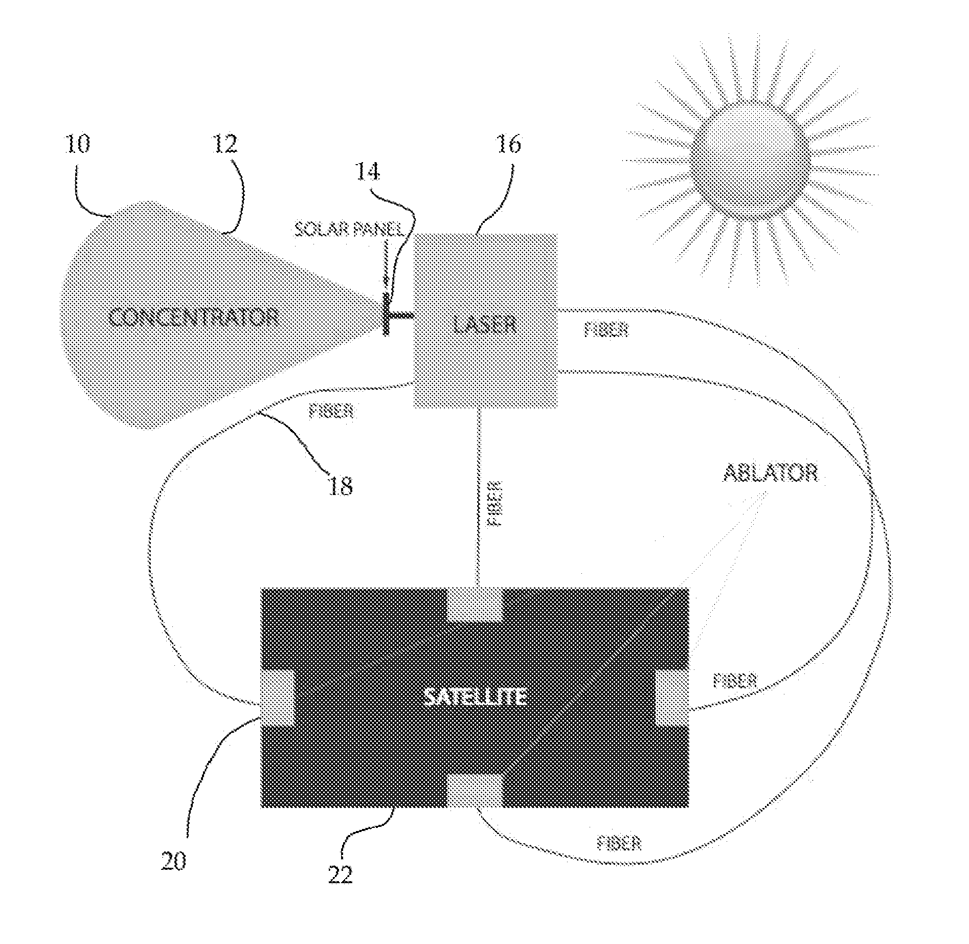
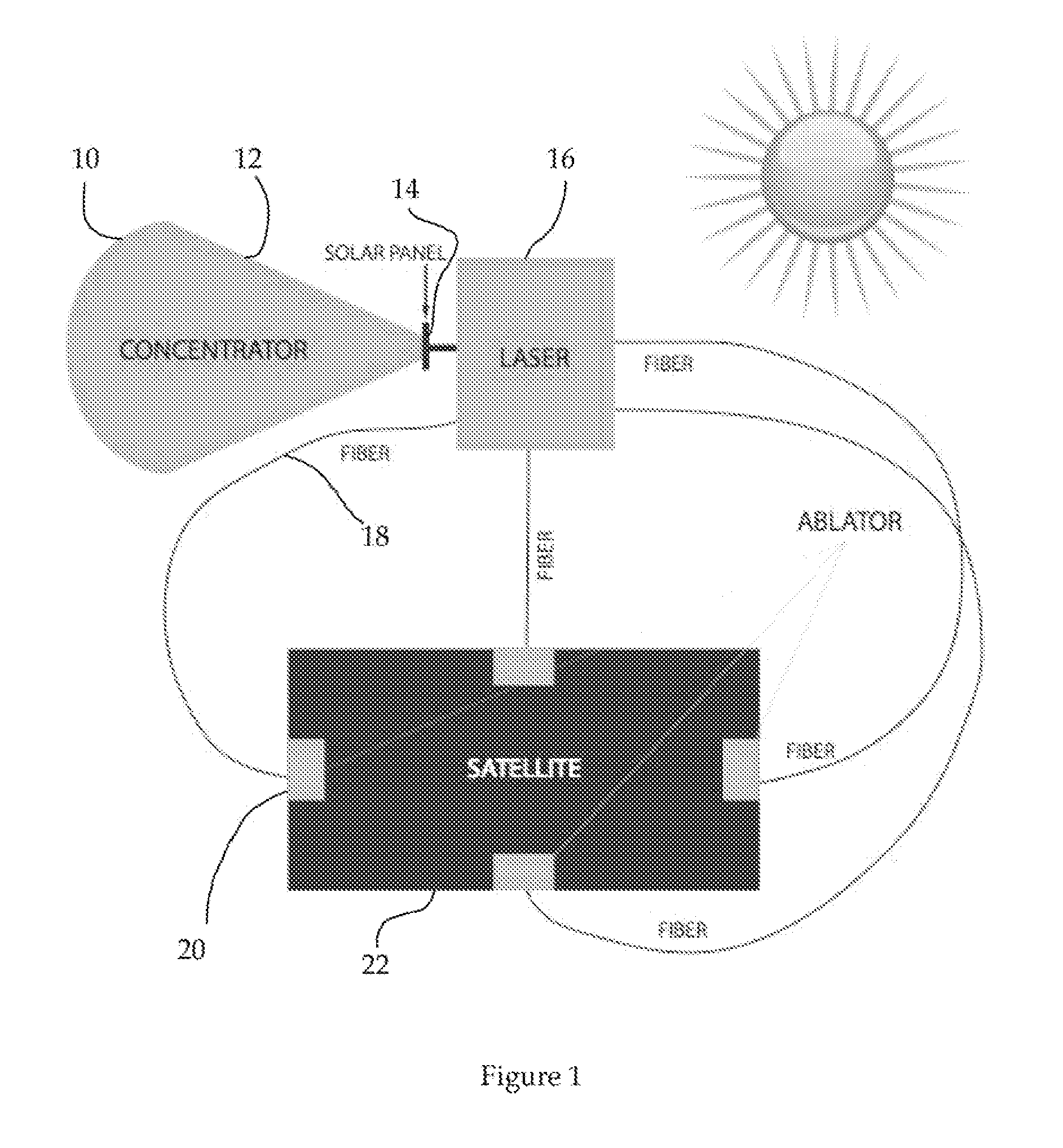
[0015]The present microthruster system utilizes a diode pumped fiber laser for the ablation driver. This scheme provides efficiency, flexibility and is lightweight. The laser power supply can be produced from a solar panel located on the satellite of interest, or the power supply can be a separate, lightweight solar system. The scheme of an embodiment of the present propulsion system is presented on FIG. 1.

[0016]In order to move the satellite in all possible directions one must have, generally, six independent motors to thrust the satellite in x, y, z directions, to provide movement forward and back. Additional motors can be required to change the satellite orientation. In a present laser scheme, this is achieved with one laser with energy delivered via fibers to different locations on the satellite where the ablation material will be located. Solar energy is used to pump the laser. As shown in the figure, a lightweight and inexpensive inflatable mirror 10 concentrates the solar rad...


PUM


Abstract

A micro-thruster for controlling the positioning of a satellite includes a solar concentrator for collecting solar energy and producing concentrated solar energy. A solar panel is positioned to receive the concentrated solar energy and thereby produces electrical energy which in turn energizes a diode-pumped fiber optic laser. The energized laser thus produces laser light which is transmitted to ejector material affixed to a satellite.

Description

CROSS-REFERENCE TO RELATED APPLICATIONS[0001]This application claims the benefit of U.S. Patent Application No. 61 / 175,333 titled “A Compact and Eco-Friendly System For Solar Power Beaming From Space To Earth,” filed May 4, 2009, incorporated herein by reference.[0002]This application is a continuation-in-part of, and claims priority to, U.S. patent application Ser. No. 12 / 773,036 titled “Systems for Solar Power Beaming from Space,” filed May 4, 2010, incorporated herein by reference.STATEMENT REGARDING FEDERALLY SPONSORED RESEARCH OR DEVELOPMENT[0003]The United States Government has rights in this invention pursuant to Contract No. DE-AC52-07NA27344 between the U.S. Department of Energy and Lawrence Livermore National Security, LLC, for the operation of Lawrence Livermore National Laboratory.BACKGROUND OF THE INVENTION[0004]1. Field of the Invention[0005]The present invention relates to the use of solar energy, laser and satellite technology, and more specifically, it relates to th...

Claims


Application Information

Patent Timeline
IPC IPC(8): H01S3/091
CPCB64G1/409B64G2001/224B64G1/44B64G1/428B64G1/2227
Inventor RUBENCHIK, ALEXANDERBEACH, RAYMOND J.DAWSON, JAY W.SIDERS, CRAIG W.
Owner LAWRENCE LIVERMORE NAT SECURITY LLC
Why Eureka
Try Eureka