Angle-multiplexing hologram recording device, method, hologram reproduction device, and method

Inactive Publication Date: 2006-05-25
PIONEER CORP
View PDF5 Cites 7 Cited by
  • Summary
  • Abstract
  • Description
  • Claims
  • Application Information

AI Technical Summary

Benefits of technology

[0038] On the contrary, the hologram reproduction apparatus of the present invention performs the calibration on the basis of the angle standard identification information and allows the subsequent prompt angle change and the prompt reproduction operation.
[0039] Thus, according to the present invention, the record density and the record capacity can be remarkably improved due to the angle-multiplex system, and the angle-multiplex type reproduction is performable accurately regardless of variations among apparatuses, and the quick reproduction operation is also allowed.
[0040] Additionally, at least one of reference light phase-code-multiplex system for performing mul

Problems solved by technology

That is, under such a mechanical state or set condition, another angle record plane different from the standard angle record plane may be adversely recognized as the standard angle record plane.
Alternatively, because of mis-recognizing the standard angle, the recording may be adversely performed to the angle record p

Method used


Image

  • Angle-multiplexing hologram recording device, method, hologram reproduction device, and method
  • Angle-multiplexing hologram recording device, method, hologram reproduction device, and method
  • Angle-multiplexing hologram recording device, method, hologram reproduction device, and method

Examples


Example

FIRST EMBODIMENT OF HOLOGRAM RECORDING APPARATUS

[0060] The first embodiment of the hologram recording apparatus of the present invention will be discussed, with reference to FIG. 1 to FIG. 3.

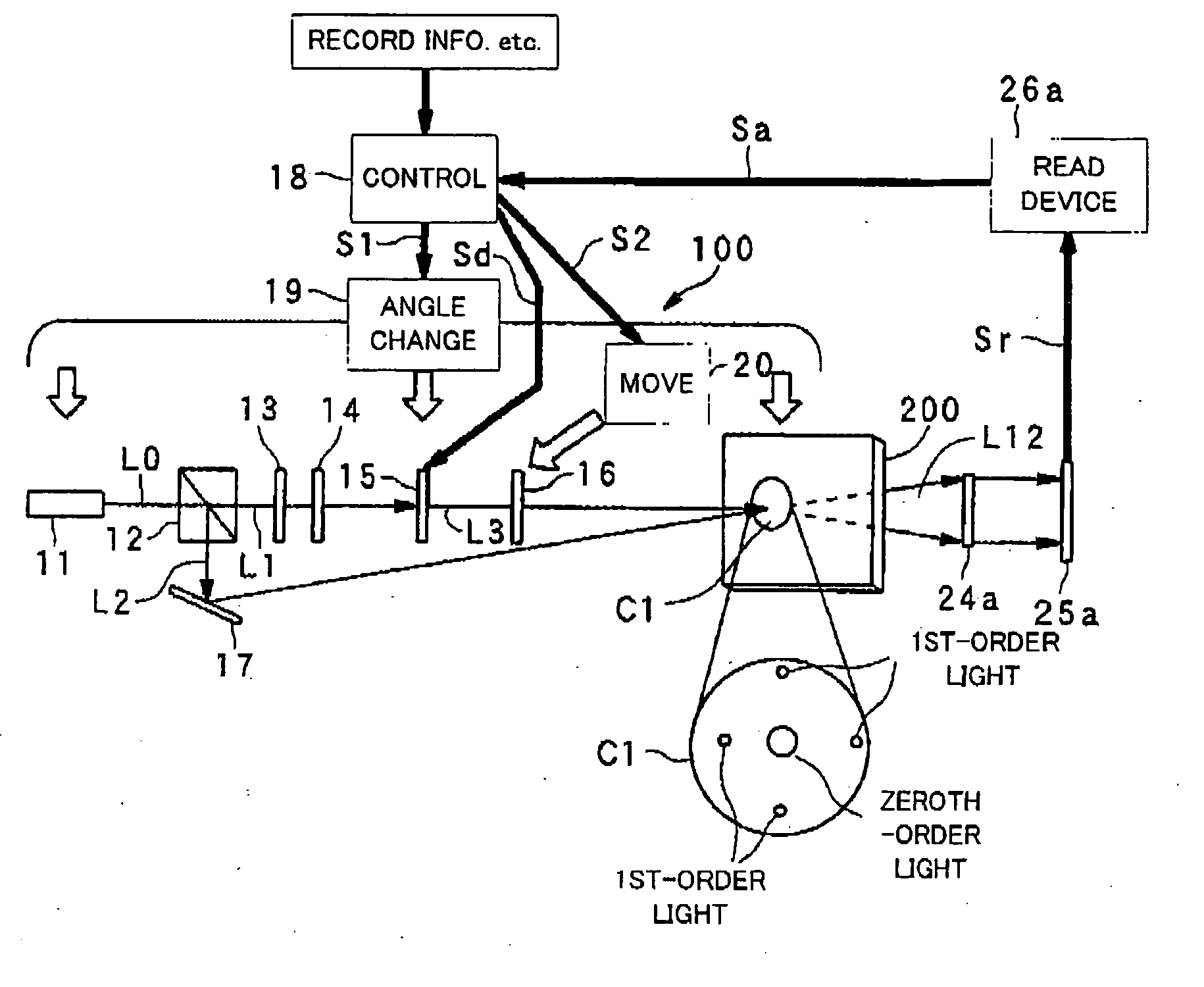
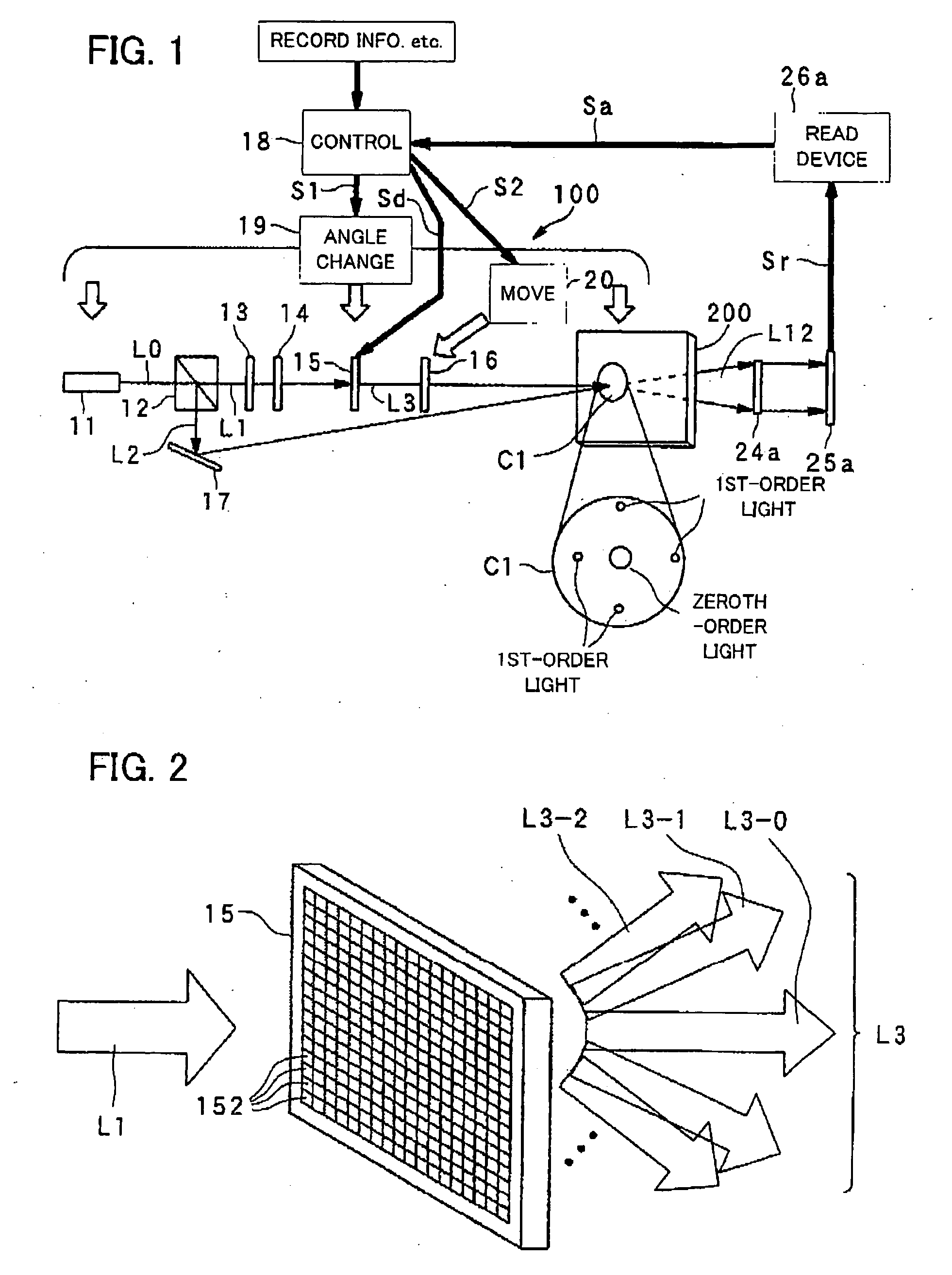
[0061] Firstly, with reference to FIG. 1 and FIG. 2, the entire configuration of the hologram recording apparatus of the present invention will be discussed. FIG. 1 illustrates the entire configuration of the hologram recording apparatus of the present invention. FIG. 2 illustrates schematically and perspectively the spatial light modulator employed in the embodiment.

[0062] As shown in FIG. 1, the hologram recording apparatus 100 in this embodiment is provided with: a laser device 11 as one example of the light source for emitting the source light L0 made of laser beam; a beam splitter 12 as one example of the optical system for splitting the source light L0 into the signal light L1 and the reference light L2; a lens 13 as one example of the enlarge optical system disposed in an optical path ...

Example

SECOND EMBODIMENT OF HOLOGRAM RECORDING APPARATUS

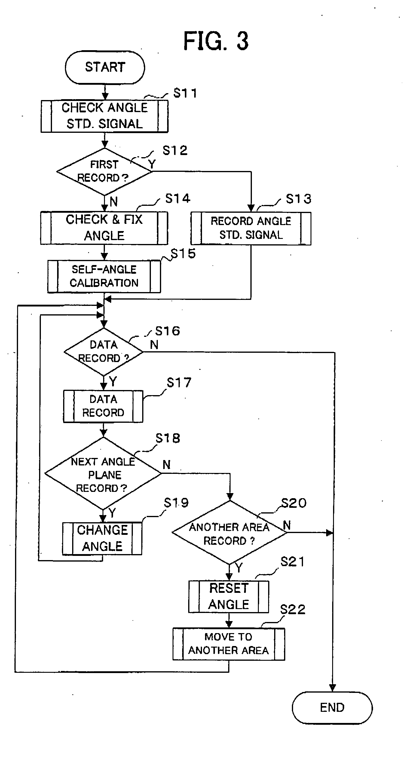
[0098] The second embodiment of the hologram recording apparatus according to the present invention will be discussed, with reference to FIG. 4. FIG. 4 is a flow chart illustrating the record operation of the hologram recording apparatus in the second embodiment.

[0099] In the second embodiment, the timing in changing the angle record plane and changing the record area is different from that of the first embodiment, and other constructions and operations are the same as those of the first embodiment. Therefore, in the flow chart of FIG. 4, the same steps as those of FIG. 3 carry the same numerals, and the explanation about them are omitted as appropriate.

[0100] Firstly in FIG. 4, the processings from step S11 to step S17 are performed similarly to the first embodiment shown in FIG. 3.

[0101] After completing the step S17, the control device 18 judges whether or not the data recording for the record information is to be performed to ...


PUM


Abstract

A hologram recording apparatus (100) includes a record angle change device (19) capable of relatively changing the record angle of a hologram recording medium (200) relative to signal light (L3) and reference light (L2); and a control device (18). The control device sets a record angle for recording a specific angle record plane as a standard record angle among a plurality of angle record planes on the hologram recording medium. Furthermore, the control device controls the record angle change device so as to change and fix the record angle after then by a predetermined angle from the set standard record angle.

Description

TECHNICAL FIELD [0001] The present invention relates to a hologram recording apparatus for and method of irradiating a hologram recording medium with signal light via a spatial light modulator to recording information and a hologram reproduction apparatus for and method of reproducing the information from the hologram recorded medium. Particularly, it relates to an angle-multiplex type hologram recording apparatus for and method of, as well as a hologram reproduction apparatus for and method of, recording different record informations overlappingly in the same area by relatively changing angles of the signal light and reference light relative to a surface of the hologram recording medium, and then reproducing the multiplex-recorded information. BACKGROUND ART [0002] Heretofore, a hologram recording apparatus, which may be provided with a liquid crystal device and the like, irradiates a spatial light modulator for modulating light depending on record information to be recorded, with ...

Claims


Application Information

Patent Timeline
IPC IPC(8): G03H1/26G03H1/04G03H1/28G11B7/0065G11B7/135G11C13/04
CPCG03H1/26G03H1/265G03H2001/0232G11B7/0065G11B7/135G11C13/042
Inventor KURODA, KAZUOSUGIURA, SATOSHIYANAGISAWA, SHUUICHITANAKA, SATORUITOH, YOSHIHISATACHIBANA, AKIHIROKUBOTA, YOSHIHISA
Owner PIONEER CORP
Why Eureka
Try Eureka