LED lamp with LEDs on a heat conductive post and method of making the LED lamp

a technology of led lamps and heat conductive posts, which is applied in the direction of semiconductor devices, light sources, lighting and heating apparatus, etc., can solve the problems of designers of such lamps, and achieve the effect of facilitating automatic manufacture of lamps

Active Publication Date: 2006-05-25
OSRAM SYLVANIA INC
View PDF14 Cites 139 Cited by
  • Summary
  • Abstract
  • Description
  • Claims
  • Application Information

AI Technical Summary

Benefits of technology

[0004] An object of the present invention is to provide a novel LED lamp, and a method of assembling the LED lamp, that includes a heat sink, a heat conductive post extended longitudinally from the heat sink where the post has longitudinal faces that each has a longitudinally extending slot therein, and a metal clad circuit board slid into each slot so that each circuit board is in thermal communication with the post where each circuit board has an exterior surface with an LED thereon. A cap may be provided on top of the post abutting lateral end surfaces of the circuit boards to hold the circuit boards in their respective slots. The circuit boards may be formed from a single integral unit that has plural that are folded into respective slots to form the circuit boards. Among other features, sliding insertion of the circuit board into the slot in the heat conductive post and / or retention of the circuit board in the slot by the cap on top of the post and / or the folding arms of a single circuit board facilitate automated manufacture of the lamp.

Problems solved by technology

The arrangement of the reflector, heat sink, circuit board, and post in an LED lamp and the efficient assembly of these components have presented problems for designers of such lamps.
One of the problems is how to provide an efficient assembly technique for connecting the LED on top of the post to a circuit board at a bottom of the post.

Method used


Image

  • LED lamp with LEDs on a heat conductive post and method of making the LED lamp
  • LED lamp with LEDs on a heat conductive post and method of making the LED lamp
  • LED lamp with LEDs on a heat conductive post and method of making the LED lamp

Examples


Embodiment Construction

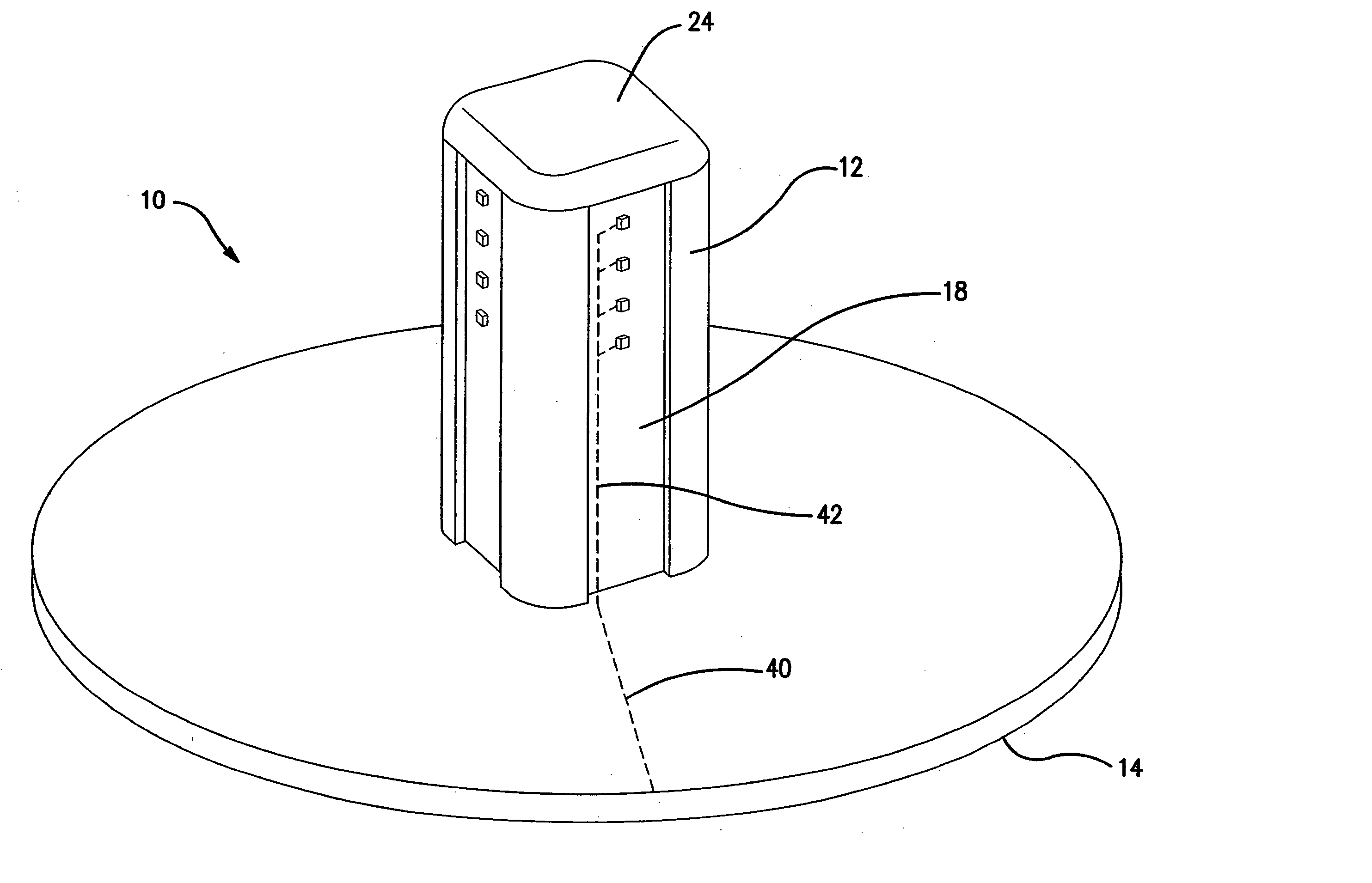
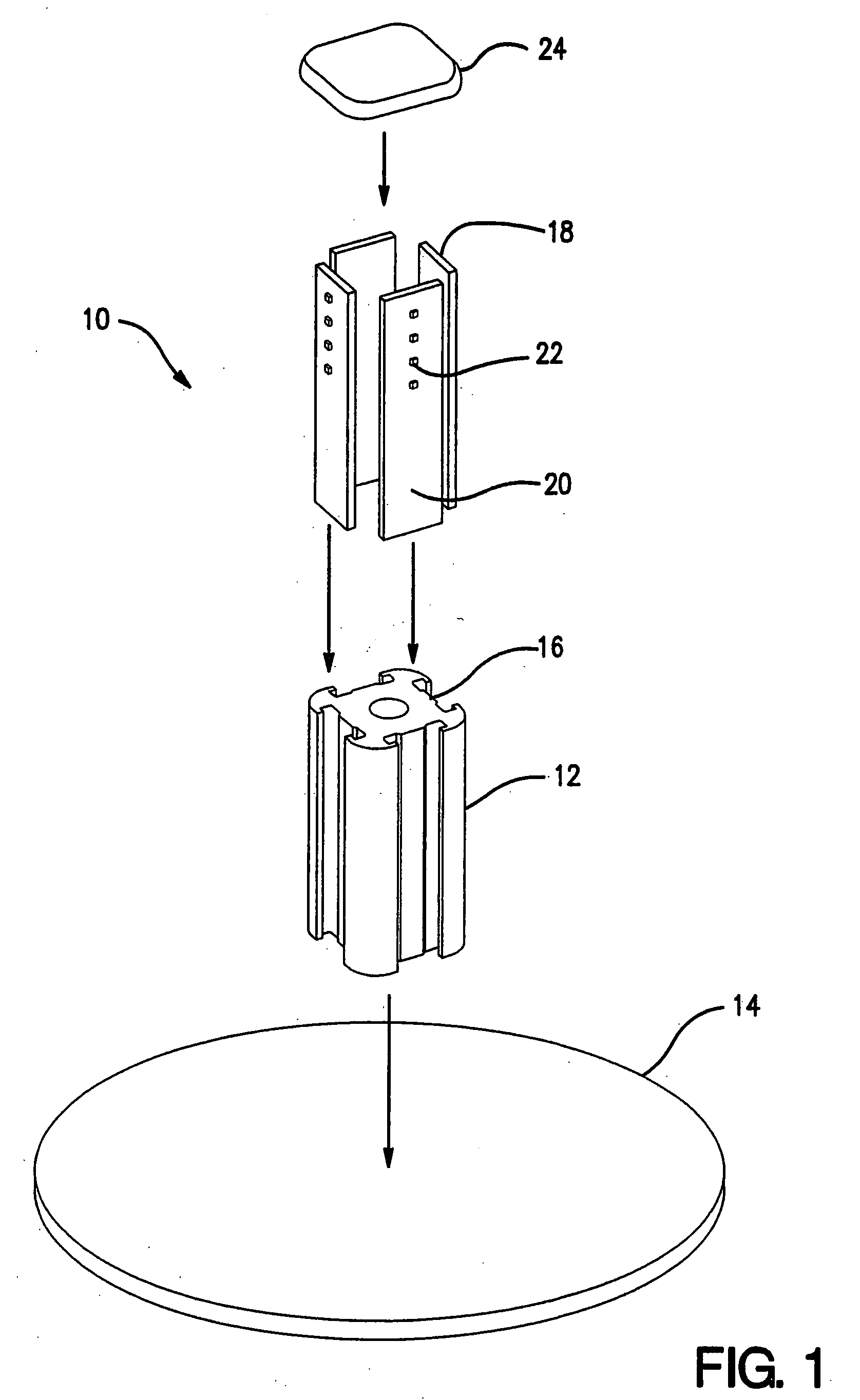
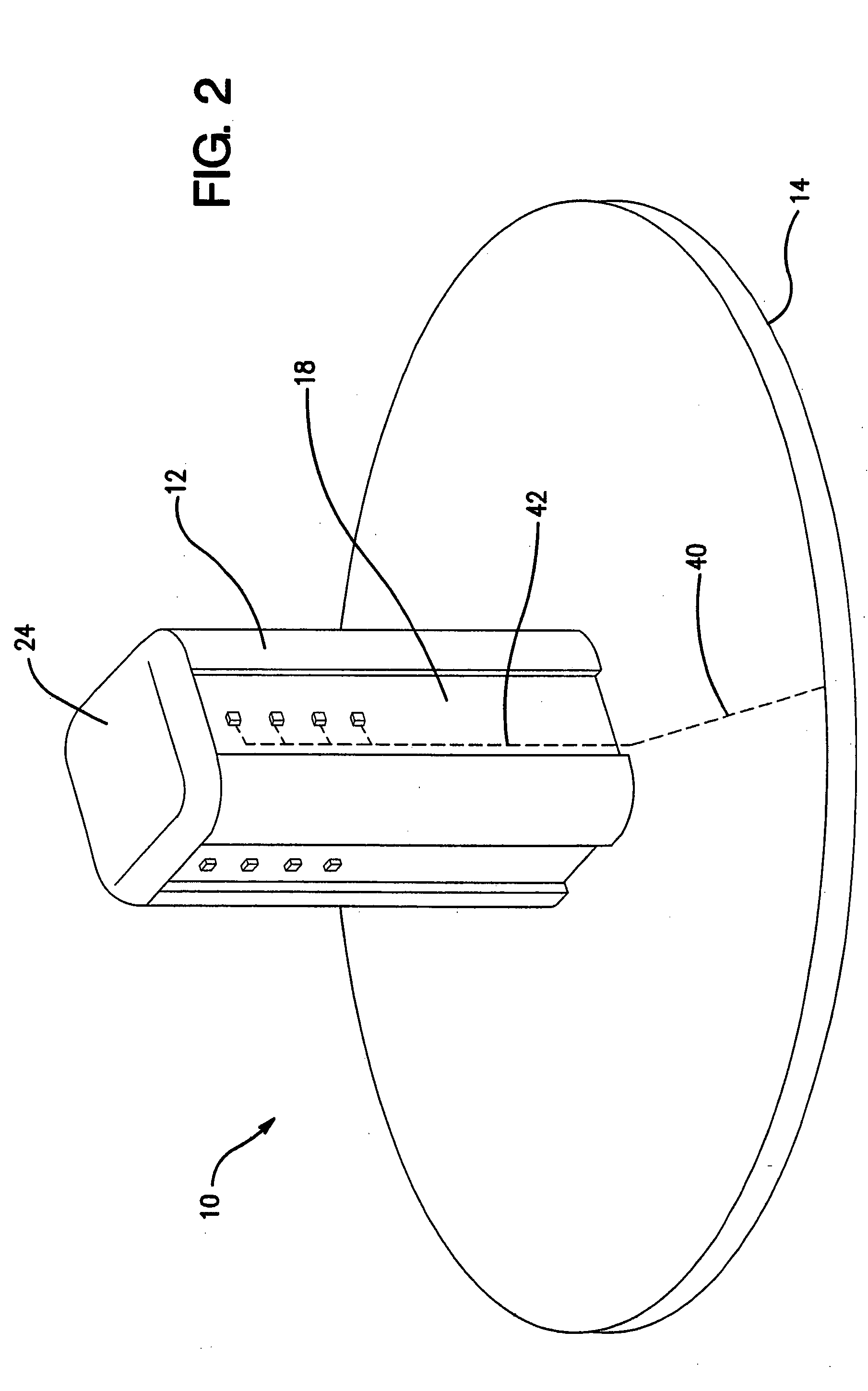
[0015] With reference now to FIGS. 1-4, an embodiment of the lamp 10 includes a heat conductive post 12 mounted on a heat conductive portion of a base 14, where the post 12 has an exterior face with a longitudinal slot 16 therein. A mounting board 18 is slideably disposed in the slot 16, where the mounting board 18 has an exterior surface 20 with an LED 22 thereon. A retaining cap 24 is attached to the post 12 opposite the base 14. The mounting board 18 may have an interference fit with the slot 16 to hold mounting board 18 in the slot 16 and provide thermal communication between the post 12 and the mounting board 18. Alternatively, or in addition, the cap 24 abuts a lateral end 26 of the mounting board 18 to hold (or help hold) the board 18 in the slot 16.

[0016] As shown in FIG. 4, each slot 16 may be provided with a longitudinal rib 16′ that presses against an interior surface of the respective one of the mounting boards 18 and longitudinal edges of the exterior surface of each o...


PUM


Abstract

A lamp, and a method of assembling the lamp, includes a heat sink, a heat conductive post extended longitudinally from the heat sink where the post has longitudinal faces that each has a longitudinally extending slot therein, a metal clad circuit board slid into each slot so that each circuit board is in thermal communication with the post where each circuit board has an exterior surface with an LED thereon, and a cap on top of the post where the cap abuts lateral end surfaces of the circuit boards. The cap may hold the circuit boards in their respective slots.

Description

BACKGROUND OF THE INVENTION [0001] The present invention relates to a lamp and a method of making a lamp in which a light emitting diode (LED) is the light source. This application relates to copending application Ser. No. 10 / 647,682 titled LED LAMP WITH INSERTABLE LED SUBSTRATES AND METHOD OF MAKING THE LAMP filed on Aug. 25, 2003 and to copending application Ser. No. 10 / 647,831 titled LED LAMP WITH INSERTABLE AXIAL WIREWAYS AND METHOD OF MAKING THE LAMP filed on Aug. 25, 2003. [0002] As is known, light output of an LED depends on its temperature. LED temperature should be kept low to ensure efficient light production. Accordingly, it is beneficial to provide an LED lamp that includes an LED with a heat sink for drawing heat away from the LED. The LED may be mounted on a post where the post is surrounded by a reflector. A circuit board provides the necessary electrical components and connections for operating the LED. The above-noted related applications and U.S. Pat. No. 6,773,138...

Claims


Application Information

Patent Timeline
Patent Type & Authority Applications(United States)
IPC IPC(8): F21V29/00F21K99/00F21V29/15H01L33/48
CPCF21K9/00F21K9/90F21V19/0045F21V19/0055F21V29/004F21V29/80F21Y2111/005H05K1/0203H05K1/14Y10S362/80F21V29/74F21Y2101/02F21Y2115/10F21Y2107/30F21V29/76
Inventor COUSHAINE, CHARLES M.TESSNOW, THOMASPETERSON, FREDALBRIGHT, KIMTAITEL, FLORENCEENG, HOWARD
Owner OSRAM SYLVANIA INC
Why Eureka
Try Eureka