
Method for allocating resources in a multicarrier system and transmission apparatus using the same

Active Publication Date: 2006-05-25
SAMSUNG ELECTRONICS CO LTD
View PDF6 Cites 68 Cited by
  • Summary
  • Abstract
  • Description
  • Claims
  • Application Information

AI Technical Summary

Benefits of technology

[0021] It is, therefore, an object of the present invention to provide a sectorization method for dividing a cell in order to minimize possible interference occurring in an OFDM / OFDMA system.
[0022] It is another object of the present invention to provide a resource allocation method for increasing a frequency reuse factor in an OFDM / OFDMA system.
[0023] It is further another object of the present invention to provide a resource allocation method for minimizing interference between an uplink and a downlink in an OFDM / OFDMA system.
[0024] It is yet another object of the present invention to provide a method for performing resource allocation on an uplink and resource allocation on a downlink in a different manner to minimize interference between the uplink and the downlink in an OFDM / OFDMA system.
[0030] It is sill another object of the present invention to provide a method for achieving efficient resource allocation in a Space Division Multiple Access (SDMA) system.

Problems solved by technology

However, the OFDM scheme had a limitation in being actually applied to a system because it should be able to implement orthogonal modulation between multiple subcarriers.
Commonly, the frequency reuse factor is fixed to 3, 4 and 7, so frequency reuse efficiency is not so high (frequency reuse factor is greater than 1) due to the fixed channel allocation technologies, and allocation of fixed subchannels leads to a high bit error rate (BER) due to frequency selective fading channels.
However, the interference balancing technology cannot perfectly accomplish advantages of multicarrier modulation such as multiuser diversity and adaptive resource allocation with channel information in base stations (BSs).
Therefore, if a particular subcarrier is used even in a neighboring cell, the FH-OFDMA system suffers severe performance degradation in an uplink, compared with the CDMA system.
If this is applied to the OFDMA system, performance degradation occurs in a location where neighboring sectors or neighboring cells use the same subcarrier.
The performance degradation is severe, especially for the uplink.

Method used


Image

  • Method for allocating resources in a multicarrier system and transmission apparatus using the same
  • Method for allocating resources in a multicarrier system and transmission apparatus using the same
  • Method for allocating resources in a multicarrier system and transmission apparatus using the same

Examples


first embodiment

[0099] a) First Embodiment for Uplink Resource Allocation

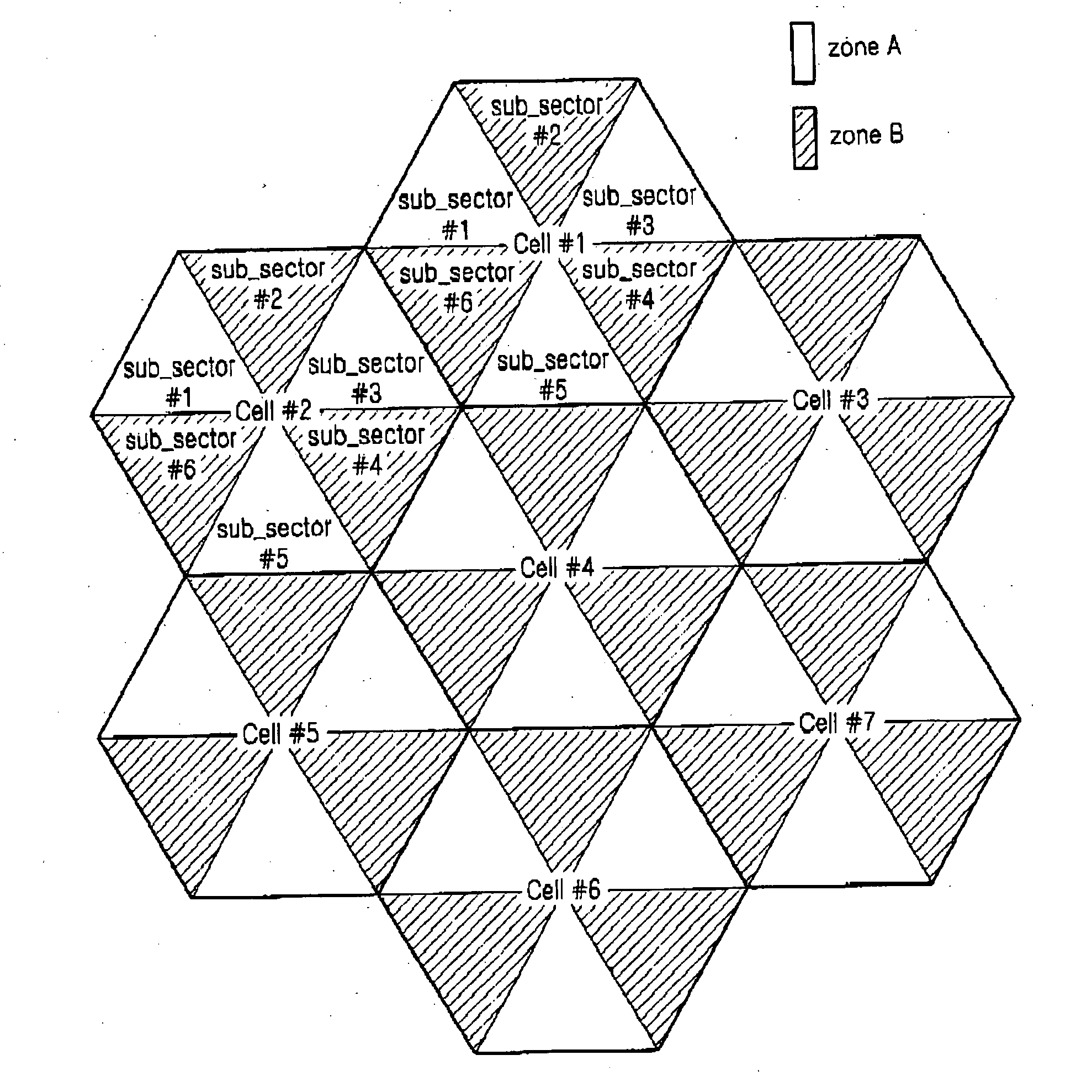
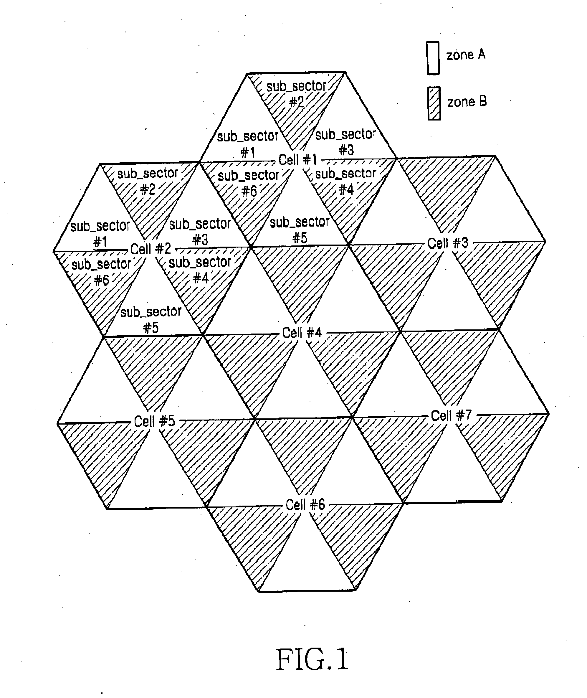
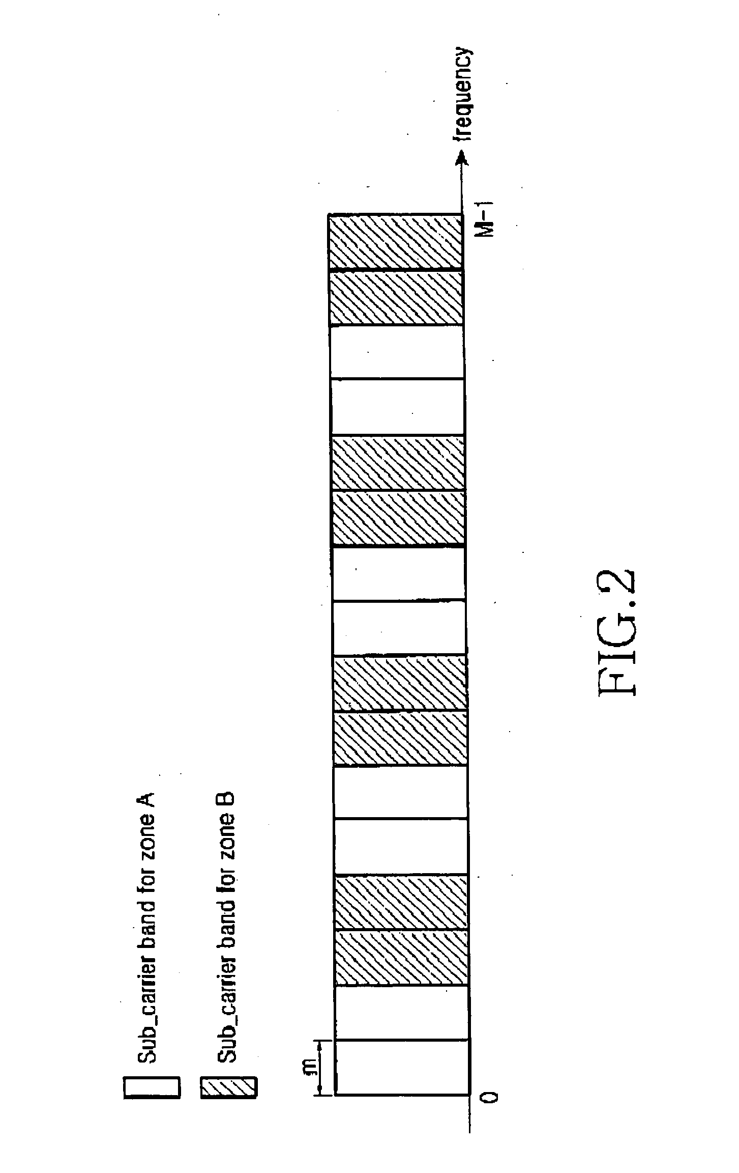
[0100] The first embodiment divides the full subcarrier band into a first subcarrier region and a second subcarrier region having the same size. The first embodiment divides the first subcarrier region into subintervals associated with the subsectors in the first service zone in the same cell, and allocates subcarriers selected in the divided subintervals as uplink resources for the subsectors in the first service zone. Similarly, the first embodiment divides the second subcarrier region into subintervals associated with the subsectors in the second service zone in the same cell, and allocates subcarriers selected in the divided subintervals as uplink resources for the subsectors in the second service zone.

[0101]FIG. 7 is a diagram illustrating an exemplary method for distributing uplink resources according to the first embodiment for uplink resource allocation. Referring to FIG. 7, the full subcarrier bandwidth (including M ...

second embodiment

[0108] b) Second Embodiment for Uplink Resource Allocation

[0109] The second embodiment for uplink resource allocation, like the first embodiment, divides the full subcarrier band into a first subcarrier region and a second subcarrier region. Further, the second embodiment divides the total subchannels allocable in the first subcarrier region into as many subchannel groups as the number of subsectors belonging to the first service zone in one cell. This is applied in the same way even for the second subcarrier region. Therefore, it is preferable to determine the total number of channels as an integer that can be divided by the number of the subsectors.

[0110] For convenience, it will be assumed herein that the total number of subchannels allocable in each of the first subcarrier region and the second subcarrier region is 60. Therefore, assuming that the total number of subchannels is 120 in this way, if the first and second service zones are each comprised of three subsectors, 20 sub...


PUM


Abstract

In an orthogonal frequency division multiplexing (OFDM) mobile communication system, an apparatus and method allocates resources for data transmission and transmits / receives user data using the allocated resources. A full subcarrier band allocable for one cell is divided into a plurality of subcarrier regions. Subcarriers selected from subcarriers existing in one of the plurality of subcarrier regions are allocated for each of a plurality of sectors constituting the cell. The subcarriers are allocated such that subcarriers existing in different subcarrier regions are allocated for neighboring sectors in the cell.

Description

PRIORITY [0001] This application claims the benefit under 35 U.S.C. § 119(a) of an application entitled “Method for Allocating Resources in a Multicarrier System and Transmission Apparatus Using the Same” filed in the Korean Intellectual Property Office on Nov. 24, 2004 and assigned Serial No. 2004-97135, the entire contents of which are incorporated herein by reference. BACKGROUND OF THE INVENTION [0002] 1. Field of the Invention [0003] The present invention relates generally to a communication system using an Orthogonal Frequency Division Multiple Access (OFDMA) scheme (hereafter referred to as an “OFDMA communication system”), and in particular, to a method for allocating resources for data transmission and an apparatus for transmitting and receiving data using the allocated resources. [0004] 2. Description of the Related Art [0005] An Orthogonal Frequency Division Multiplexing (OFDM) scheme can be defined as a two-dimensional access scheme obtained by combining time division acc...

Claims


Application Information

Patent Timeline
IPC IPC(8): H04J1/00H04J11/00H04W16/02H04W16/12H04W16/24H04W16/28
CPCH04W16/02H04W16/12H04W16/24H04W16/28H04W28/16H04L27/26
Inventor PARK, SEUNG-YOUNGLEE, YEON-WOOYUN, SANG-BOHKIM, YUNG-SOO
Owner SAMSUNG ELECTRONICS CO LTD
Learn More