Fan-beam and cone-beam image reconstruction using filtered backprojection of differentiated projection data

a technology of projection data and filtered backprojection, applied in the field of computed tomography (ct) imaging apparatus, can solve the problems of difficult generalization of the success of radon transformation, radon space and radon transformation reconstruction methodology, and the inability of the detector to align rigidly

Active Publication Date: 2006-05-25
WISCONSIN ALUMNI RES FOUND
View PDF14 Cites 36 Cited by
  • Summary
  • Abstract
  • Description
  • Claims
  • Application Information

AI Technical Summary

Problems solved by technology

However, unlike in the other scanners, the detectors are not aligned rigidly relative to the x-ray beam.
The Radon space and Radon transformation reconstruction methodology is more problematic when applied to three-dimensional image reconstruction.
The reason for this difficulty is that the simple relation between the Radon transform and the x-ray projection transform for the 2D case in not valid in the 3D cone beam case.
Consequently, we have difficulty generalizing the success of the Radon transform as applied to the 2D fan beam reconstruction to the 3D cone beam reconstruction.
In other words, we have not managed to derive a shift-invariant FBP method by directly rebinning the measured cone beam data into Radon space.
But image reconstruction from divergent-beam projections poses a challenge.
In particular, the PST is not directly applicable to the divergent-beam projections since the shift-invariance in a single view of projections is lost in the divergent-beam cases.
There are some issues on the potential loss of image spatial resolution due to the data rebinning.
The disadvantage of the convolution-based method is that the weight in the backprojection step depends on the individual image pixels and thus noise distribution may not be uniform.
This may pose problems in the clinical interpretation of tomographic images.
In the cone-beam case, it is much more complicated to rebin cone-beam projections into parallel-beam projections.
The huge cone-beam data set also poses a big challenge to the potential data storage during the rebinning process.
s will cause non-uniform distribution of the image noise. Mor
s will potentially lead to some data inconsistency in dynamic imaging. Fin
ally, the current convolution-based image reconstruction algorithms are only valid for some discrete pitch values in the case of helical / spiral source trajectory. Thi
s feature limits their application in a helical / spiral cone-beam CT scanner.

Method used


Image

  • Fan-beam and cone-beam image reconstruction using filtered backprojection of differentiated projection data
  • Fan-beam and cone-beam image reconstruction using filtered backprojection of differentiated projection data
  • Fan-beam and cone-beam image reconstruction using filtered backprojection of differentiated projection data

Examples


Embodiment Construction

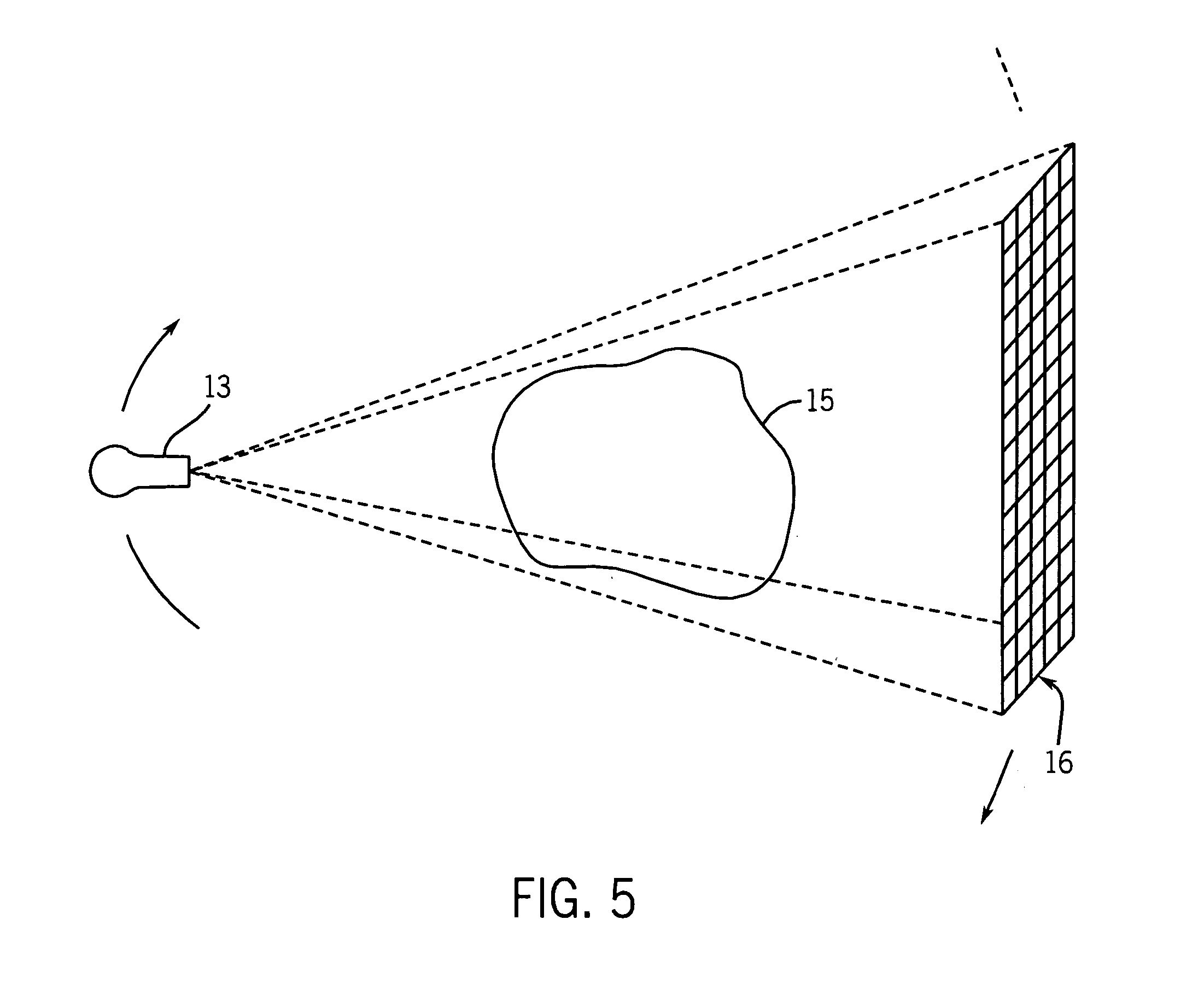
[0066] With initial reference to FIGS. 6 and 7, a computed tomography (CT) imaging system 10 includes a gantry 12 representative of a “third generation” CT scanner. Gantry 12 has an x-ray source 13 that projects a cone beam of x-rays 14 toward a detector array 16 on the opposite side of the gantry. The detector array 16 is formed by a number of detector elements 18 which together sense the projected x-rays that pass through a medical patient 15. Each detector element 18 produces an electrical signal that represents the intensity of an impinging x-ray beam and hence the attenuation of the beam as it passes through the patient. During a scan to acquire x-ray projection data, the gantry 12 and the components mounted thereon rotate about a center of rotation 19 located within the patient 15.

[0067] The rotation of the gantry and the operation of the x-ray source 13 are governed by a control mechanism 20 of the CT system. The control mechanism 20 includes an x-ray controller 22 that prov...


PUM

PropertyMeasurementUnit
angleaaaaaaaaaa
cone anglesaaaaaaaaaa
fan angleaaaaaaaaaa

Abstract

A tomographic image reconstruction method produces either 2D or 3D images from fan beam or cone beam projection data by filtering the backprojection image of differentiated projection data. The reconstruction is mathematically exact if sufficient projection data is acquired. A cone beam embodiment and both a symmetric and asymmetric fan beam embodiment are described.

Description

CROSS-REFERENCE TO RELATED APPLICATIONS [0001] This application is based on U.S. Provisional Patent Application Serial No. 60 / 630,930, filed on Nov. 24, 2004 and entitled “FAN-BEAM AND CONE-BEAM IMAGE RECONSTRUCTION USING FILTERED BACKPROJECTION OF DIFFERENTIATED PROJECTION DATA,” and U.S. Provisional Patent Application Serial No. 60 / 630,932, filed on Nov. 24, 2004 and entitled “FAN-BEAM IMAGE RECONSTRUCTION METHOD FOR TRUNCATED PROJECTION DATA.”STATEMENT REGARDING FEDERALLY SPONSORED RESEARCH [0002] This invention was made with government support under Grant No. EB001683 awarded by the National Institute of Health. The United States Government has certain rights in this invention.BACKGROUND OF THE INVENTION [0003] The present invention relates to computed tomography (CT) imaging apparatus; and more particularly, to a method for reconstructing images from divergent beams of acquired image data. [0004] In a current computed tomography system, an x-ray source projects a fan-shaped bea...

Claims


Application Information

Patent Timeline
Patent Type & Authority Applications(United States)
IPC IPC(8): H05G1/60A61B6/00G01N23/00G21K1/12
CPCG06T11/006G06T2211/416G06T2211/421A61B6/027
Inventor CHEN, GUANG-HONG
Owner WISCONSIN ALUMNI RES FOUND
Why Eureka
Try Eureka