Optical receiver having transient compensation

a transient compensation and optical receiver technology, applied in the field of optical receivers, can solve the problems of high installation cost for retrofitting into existing systems, low cost, and inability to detect errors, and achieve the effect of improving the bit error rate (ber) performance and low cos

Inactive Publication Date: 2006-05-25
LUMENTUM FIBER OPTICS INC
View PDF6 Cites 18 Cited by
  • Summary
  • Abstract
  • Description
  • Claims
  • Application Information

AI Technical Summary

Benefits of technology

[0008] The optical receiver of the present invention has the benefit of using low cost electrical circuitry contained within the receiv

Problems solved by technology

When the decision threshold level is fixed, any variation or transient in average power of the incoming signal can lead to bit errors.
This has been done with variable gain erbium-doped fiber amplifie

Method used


Image

  • Optical receiver having transient compensation
  • Optical receiver having transient compensation
  • Optical receiver having transient compensation

Examples


Embodiment Construction

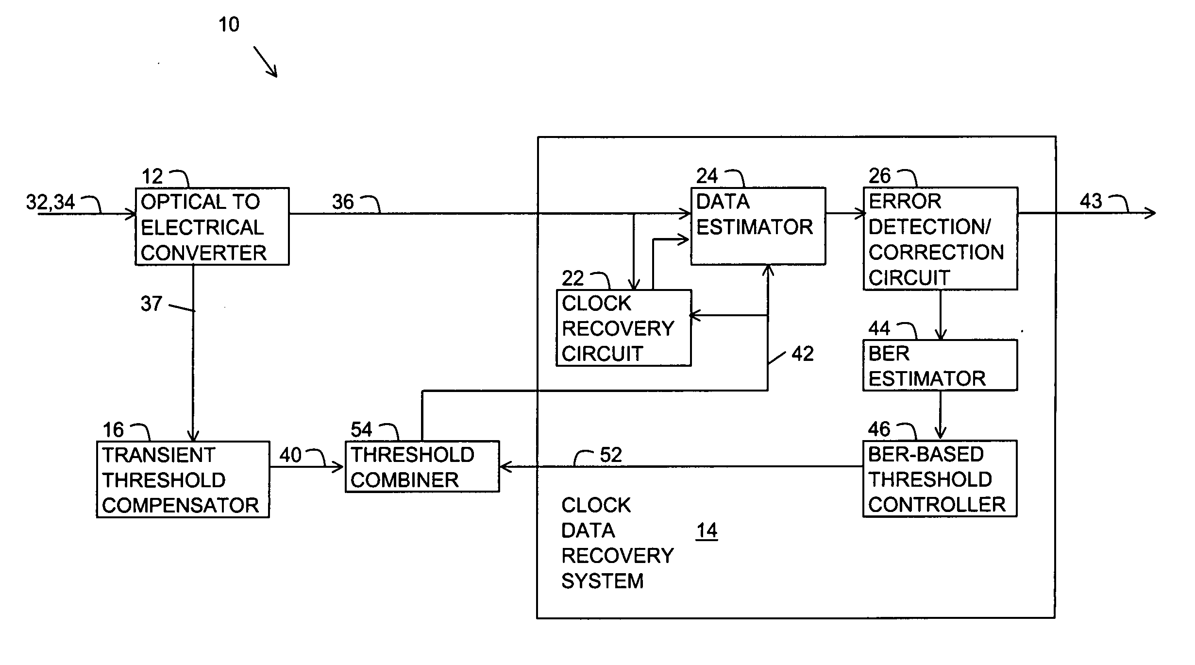
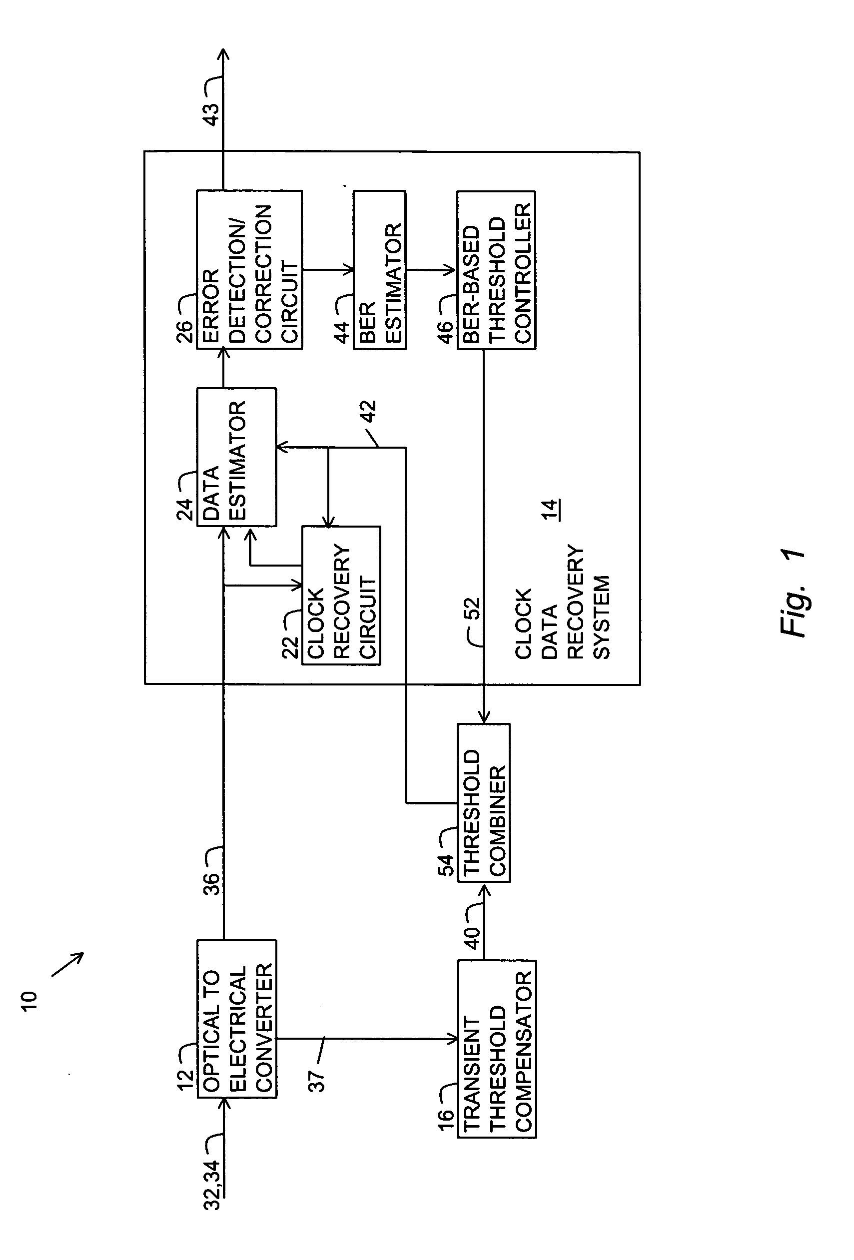
[0014]FIG. 1 is a block diagram of a receiver of the present invention referred to with a reference number 10. The receiver 10 includes an optical to electrical (OE) converter 12, a clock and data recovery (CDR) system 14 and a transient threshold compensator 16. The CDR system 14 includes a clock recovery circuit 22, a data estimator 24, and an error detection / correction circuit 26. It should be noted that a “circuit” typically includes both hardware and software. The receiver 10 may also include other components such as optical and electrical demultiplexers, amplifiers and filters.

[0015] The OE converter 12 couples to an optical link 32 for receiving an incoming amplitude or intensity modulated optical signal 34 and converting the signal 34 to a modulated electrical signal 36. The modulated electrical signal 36 may be baseband where the modulation is the signal 36, or the modulation may be carried on an intermediate frequency carrier signal. In either case, the pattern and rate o...


PUM


Abstract

An optical receiver having compensation for signal level transients. The receiver includes an OE converter, a transient threshold compensator, a threshold combiner and a CDR system. The OE converter receives the incoming optical signal and provides a modulated electrical signal having a high speed response for tracking the modulation on the optical signal and an averaged electrical signal having a moderate speed response for tracking changes in the average level of the optical signal. The transient threshold compensator processes the averaged electrical signal for providing a transient feedforward adjustment. The threshold combiner combines the transient feedforward adjustment with a lower speed BER feedback threshold adjustment for providing a decision threshold signal. The CDR system uses the decision threshold signal for recovering a clock, providing the BER feedback threshold adjustment, and estimating the data carried by the modulation.

Description

BACKGROUND OF THE INVENTION [0001] 1. Field of the Invention [0002] The invention relates generally to optical receivers and more particularly to an optical receiver having signal level transient compensation. [0003] 2. Description of the Background Art [0004] Optical transmission systems include a transmitter for transmitting a modulated optical signal into a link and a receiver for receiving the signal from the link. The link may span a short distance or thousands of kilometers. Existing optical receivers have an optical to electrical (OE) converter, typically using a photodiode, for converting the incoming optical signal to an electrical signal. The electrical signal drives a clock data recovery (CDR) system that recovers the clock and then uses the clock for sampling the electrical signal. The modulated data is recovered by comparing the sampled signal to a fixed decision threshold level. A sampled signal level that is above the threshold level yields a bit sense of one and a le...

Claims


Application Information

Patent Timeline
IPC IPC(8): H04B10/06
CPCH04B10/695
Inventor WANG, GARY
Owner LUMENTUM FIBER OPTICS INC
Why Eureka
Try Eureka