Working machine for circuit board and method of feeding component thereto

a technology of working machine and circuit board, which is applied in the direction of metal-working machine components, manufacturing tools, instruments, etc., can solve the problems of not being easy for the operator, reducing the overall size of electronic-circuit-component mounting apparatuses, and unable to easily gain access to the inner space of each apparatus

Active Publication Date: 2006-05-25
FUJI MASCH MFG CO LTD
View PDF10 Cites 41 Cited by
  • Summary
  • Abstract
  • Description
  • Claims
  • Application Information

AI Technical Summary

Benefits of technology

[0015] The present invention is obtained by applying the invention according to the mode (1), to the supply of suction nozzle or nozzles to the component mounting apparatus. Recently, the number of sorts of electronic-circuit components to be mounted by an electronic-circuit-component mounting apparatus has been increased, and accordingly the number of sorts of suction nozzles needed to mount those components has been increased. Therefore, the present invention is very advantageous. The present invention is particularly advantageously applied to an X-Y-robot-type electronic-circuit-component mounting apparatus wherein a mounting head is moved by an X-Y robot. However, the present invention can be applied to a head-revolution-type electronic-circuit-component mounting apparatus wherein a plurality of mounting heads are intermittently revolved about a common axis line, while a circuit substrate is moved by an X-Y table to an arbitrary position on an X-Y coordinate plane, and a component supplying device is moved in a direction tangent to a locus of revolution of each of the mounting heads. In the latter case, each mounting head can be stopped at only a predetermined position. However, since the substrate holding device that holds the circuit substrate conveyed by the substrate conveyor, is held and moved by the X-Y table, the nozzle carrier plate can be moved, in place of the circuit substrate, by the X-Y table to an arbitrary position on the X-Y coordinate plane, and accordingly can be positioned at an arbitrary position relative to the each mounting head. Though at least a portion of the substrate holding device may be provided by at least a portion of the substrate conveyor, the substrate holding device may be provided completely independent of the substrate conveyor.

Problems solved by technology

However, depending upon a specific construction of the electronic-circuit-component mounting apparatus, it may not be easy for the operator to place the nozzle stocker at the predetermined position.
For example, recently, the overall size of electronic-circuit-component mounting apparatuses has been reduced to such an extent that an operator cannot easily gain access to an inner space of each apparatus.
However, similar problems generally occur to the substrate-related-operation performing apparatus, such as an adhesive dispenser that applies adhesive in the form of spots, to a circuit substrate so as to fix electronic-circuit components to the substrate, or an inspecting apparatus that inspects an electronic circuit such as a produced printed circuit board.

Method used


Image

  • Working machine for circuit board and method of feeding component thereto
  • Working machine for circuit board and method of feeding component thereto
  • Working machine for circuit board and method of feeding component thereto

Examples


Embodiment Construction

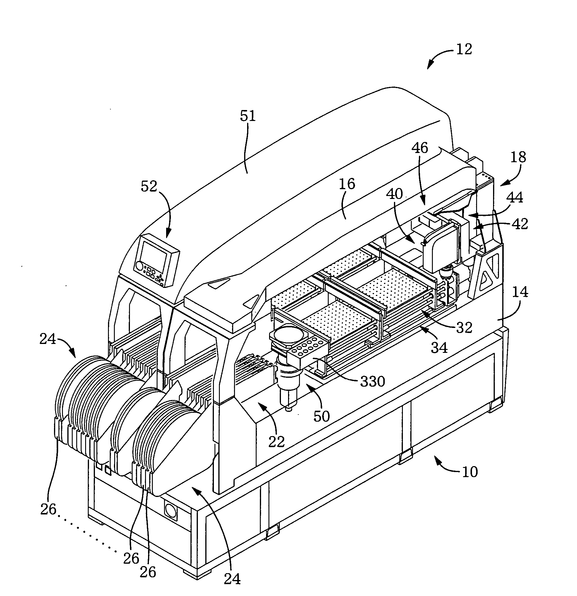
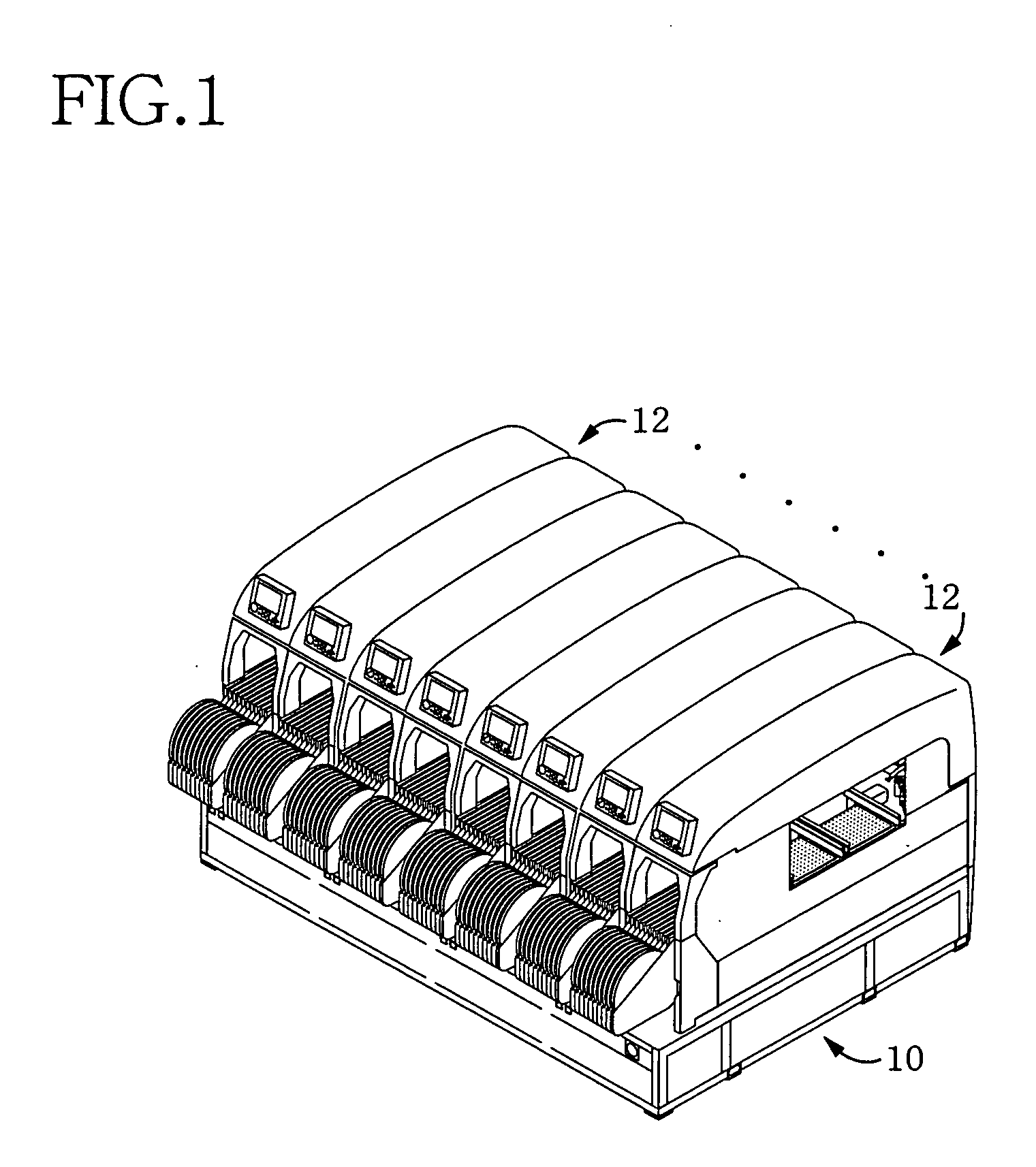
[0073]FIG. 1 shows one basic embodiment of a circuit-substrate-related-operation performing system. More specifically described, the basic system shown in FIG. 1 is an electronic-circuit-component mounting system (hereinafter, abbreviated to the “mounting system” where appropriate) that performs an electronic-circuit-component mounting operation. The mounting system includes a system base 10, and a plurality of mounting modules 12 each as an electronic-circuit-component mounting apparatus that have respective identical constructions and that are arranged adjacent to each other, and are oriented in a same direction, in a mounting-apparatus line. A direction in which the mounting modules 12 are arranged will be referred to as an X-axis direction; and a direction perpendicular to the X-axis direction on a horizontal plane will be referred to as a Y-axis direction.

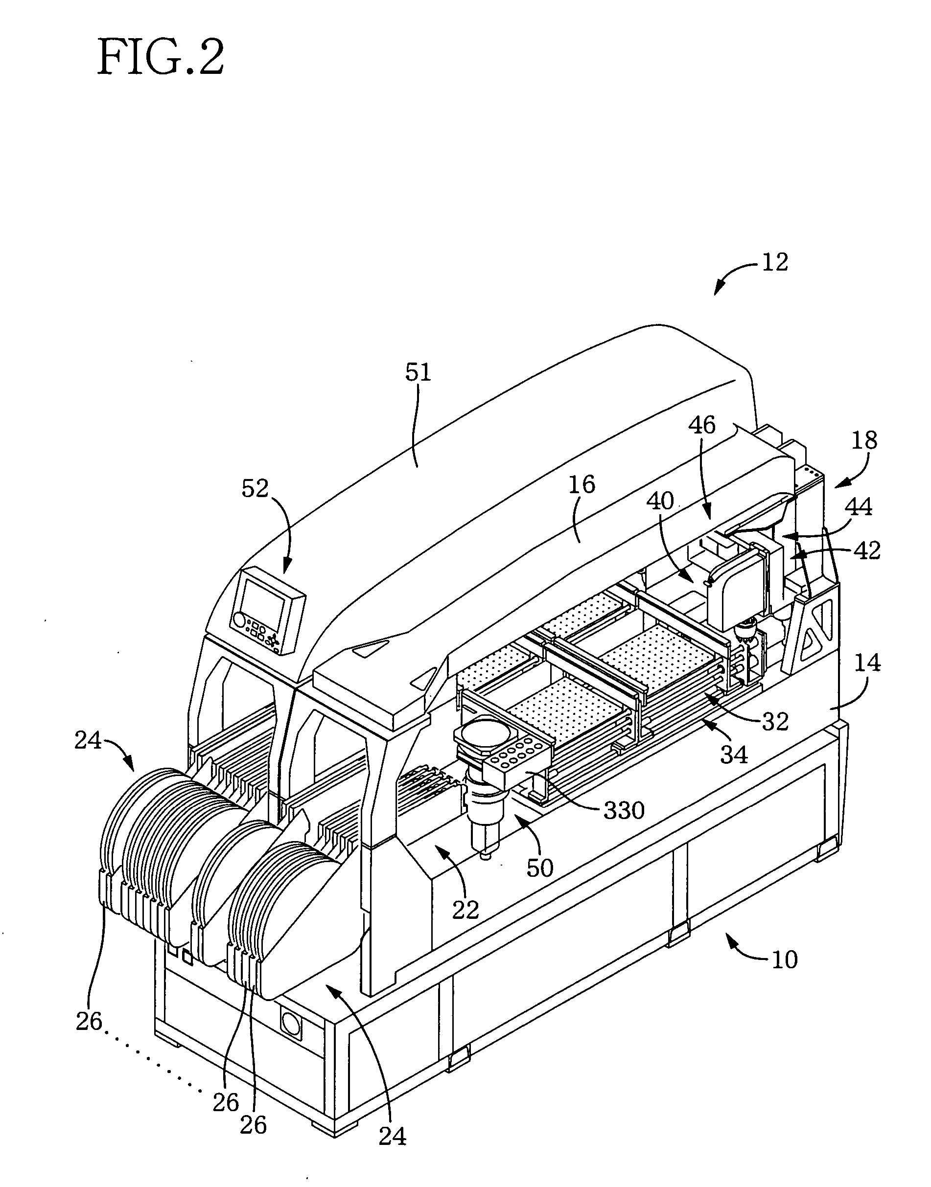
[0074]FIG. 2 is a perspective view of two mounting modules 12 of the above-indicated mounting system, in a state in which a...


PUM

PropertyMeasurementUnit
angular phaseaaaaaaaaaa
sizeaaaaaaaaaa
suctionaaaaaaaaaa

Abstract

A component mounting apparatus including an exchangeable suction nozzle is easily supplied with another suction nozzle to replace the former suction nozzle. A plurality of mounting modules 12 having respective identical constructions are arranged adjacent to each other such that the mounting modules are oriented in a same direction, so that the mounting modules 12 constitute a mounting-apparatus line. When the mounting-apparatus line is reset, a mounting head 40 is used to exchange automatically suction nozzles 158 between a nozzle stocker 330 and a nozzle carrier plate 400, so that a current arrangement of suction nozzles on the nozzle stocker 330 is changed to a new arrangement of suction nozzles for the next component mounting operation. The nozzle carrier plate 400 can hold a plurality of sorts of suction nozzles 158 that are needed for the next component mounting operation but are not held by the mounting modules 12. A wiring-board conveying device 34 is used to convey sequentially the nozzle carrier plate 400 to each of the mounting modules 12 and, in a state in which the nozzle carrier plate 400 is positioned and held, one or more unnecessary suction nozzles 158 are returned to the nozzle carrier plate 400 and one or more suction nozzles 158 needed for the next mounting operation are held by one or more vacant nozzle holders.

Description

TECHNICAL FIELD [0001] The present invention relates to a substrate-related-operation performing apparatus that performs a predetermined operation related to a circuit substrate such as a printed wiring board, and particularly to the art of supplying an exchangeable constituent element of a substrate-related-operation performing apparatus. BACKGROUND ART [0002] In a substrate-related-operation performing apparatus such as an electronic-circuit-component mounting apparatus that mounts an electronic-circuit component on a circuit substrate, if a current sort of circuit substrates are changed to a new sort of circuit substrates, it is often desirable to change at least one constituent portion of the apparatus. To this end, the apparatus includes at least one constituent element that is detachably attached thereto, and the current constituent element corresponding to the current sort of circuit substrates is exchanged with another constituent element corresponding to the new sort of cir...

Claims


Application Information

Patent Timeline
Patent Type & Authority Applications(United States)
IPC IPC(8): B23Q3/155H01R43/00H05K13/04
CPCH05K13/0408Y10T483/134Y10T483/10Y10T29/53191Y10T29/4913Y10T483/17Y10T29/5193H05K13/0409
Inventor YASUI, YOSHIHIRO
Owner FUJI MASCH MFG CO LTD
Why Eureka
Try Eureka