Articulating spinal disc prosthetic

a spinal disc and prosthetic technology, applied in the field of prosthetics, can solve the problems of increasing the difficulty of cervical disc prosthetics, requiring an extremely high fatigue limit, and affecting the quality of spinal disc prosthetics, so as to improve reliability and durability, improve wear resistance, and improve durability. the effect of durability

Inactive Publication Date: 2006-05-25
AFLATOON KAMRAN +1
View PDF4 Cites 60 Cited by
  • Summary
  • Abstract
  • Description
  • Claims
  • Application Information

AI Technical Summary

Benefits of technology

[0017] In accordance with the foregoing object, the present invention comprises a lumbar and/or cervical disc prosthetic formed with three primary layers, including a superior (upper) plate, inferior (lower) plate, and intermediate layer, in a sandwiched configuration. The superior plate member is adapted to be secured on one side to an upper vertebra in a spinal column, and has a formed concave side exposed downwardly. The inferior plate member is adapted to be secured on one side to a lower vertebra in the spinal column, and has a substantially flat side exposed upwardly. The flat side is interrupted by a central cylindrical recess. The intermediate member has a convex side conforming to the concave side of the superior plate member, a flat downside conforming to the flat side of said inferior plate member, and is sandwiched between the superior and inferior plate members. The flat upside of the inferior member is...

Problems solved by technology

Intervertebral discs are subject to various forms of damage and degeneration due to mechanical stresses and aging.
Cervical disc prosthetics pose a more difficult challenge in that the intervertebral spacing of the cervical vertebrae is smaller than for the lower vertebrae, etc., on the order of 8-9 mm for the cervical vertebrae, as compared with approximately 11 mm for the intervertebral discs.
This requires an extremely high fatigue limit.
Whi...

Method used


Image

  • Articulating spinal disc prosthetic
  • Articulating spinal disc prosthetic
  • Articulating spinal disc prosthetic

Examples


Embodiment Construction

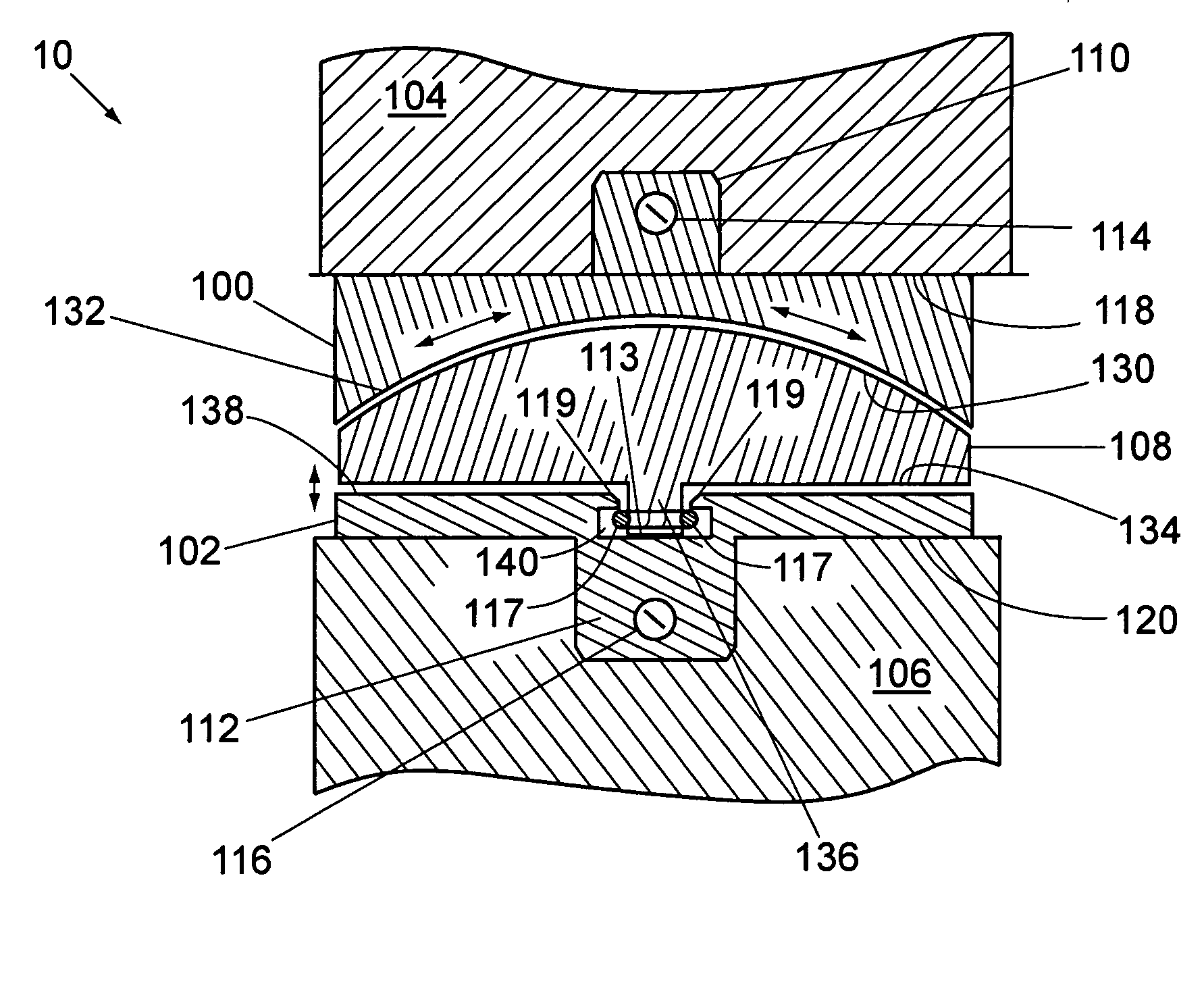
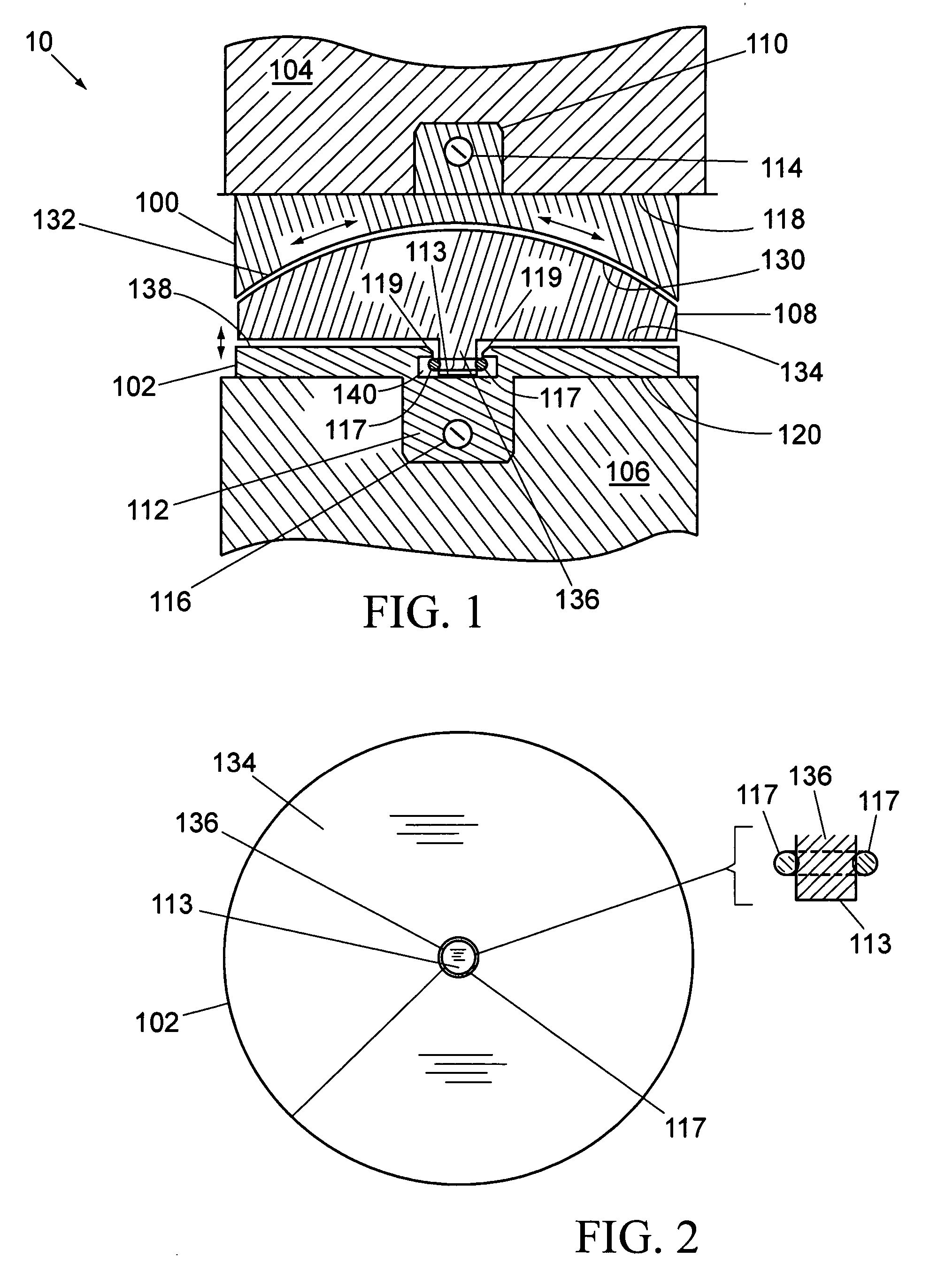
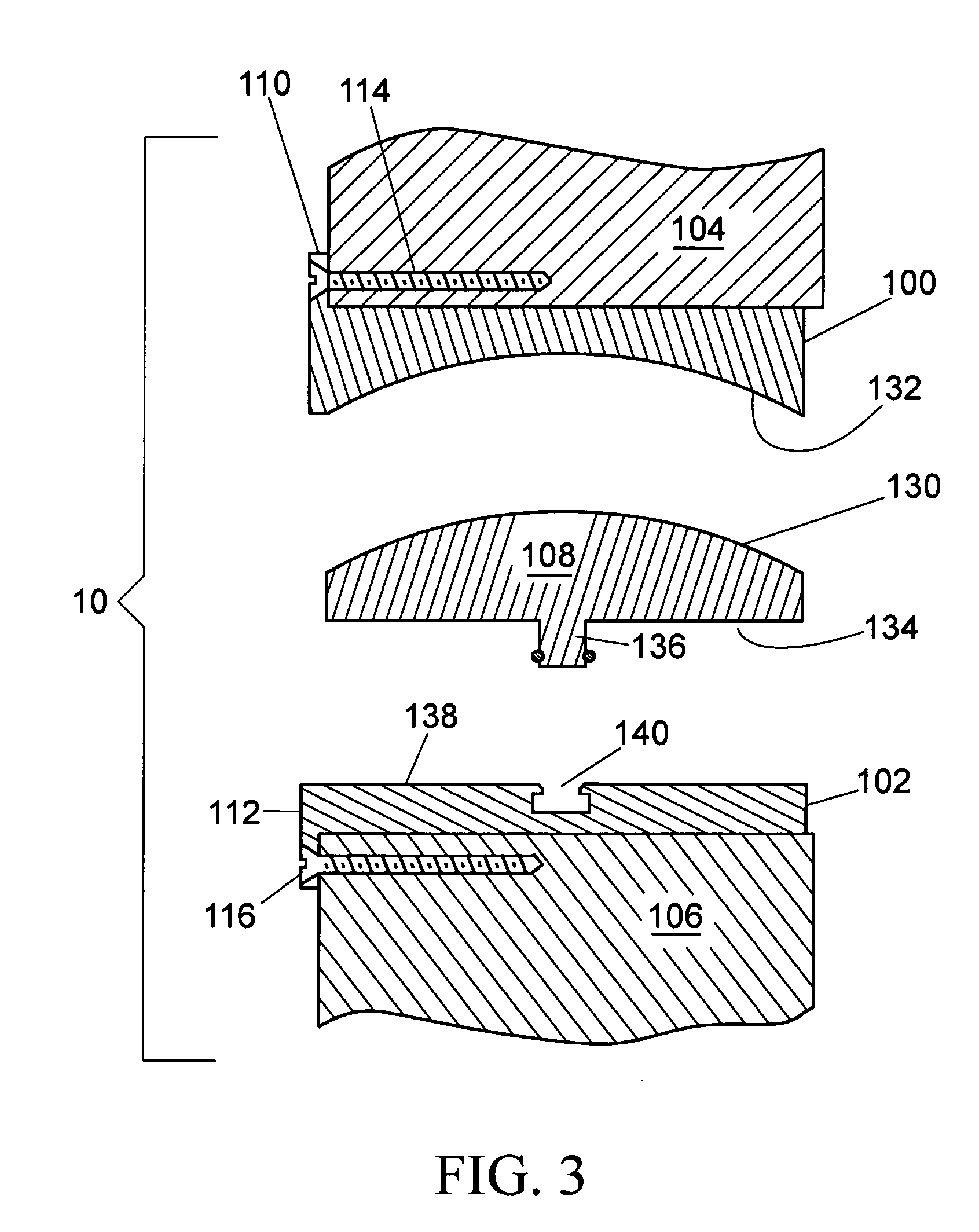
[0034]FIGS. 1-3 are a side view, bottom plan view, and exploded view, respectively, of the spinal disc prosthesis 10 (lumber or cervical) according to a preferred embodiment of the present invention. Referring to all of FIGS. 1-3, the spinal disc prosthesis 10 as illustrated includes an upper, or superior, plate member 100, and a lower, or inferior, plate member 102, which are adapted to be secured to upper and lower vertebra 104, 106, respectively, in a spinal column. An intermediate member 108 is provided, and is disposed between the upper and lower plate members 100, 102, once the prosthesis is assembled in the spinal column.

[0035] It is to be noted that the reference to the plate members as upper and lower members is for the purpose of identifying these members in the drawings. It may well be possible that the positions of the two plate members can be reversed.

[0036] Each of upper and lower plate members 100, 102 is provided with means for securement to the upper and lower ver...


PUM


Abstract

A spinal disc prosthetic for replacement of cervical and/or lumber discs, that in each case allows a limited degree of rotational articulation, as well as durability and resistance to fatigue. The prosthetic is formed with three primary layers, including a superior (upper) plate, inferior (lower) plate, and intermediate layer, in a sandwiched configuration. The superior plate member is adapted to be secured on one side to an upper vertebra in a spinal column, and has a formed concave side exposed downwardly. The inferior plate member is adapted to be secured on one side to a lower vertebra in the spinal column, and has a substantially flat side exposed upwardly. The intermediate member is sandwiched between the superior and inferior plate members with conforming sides, and a short cylindrical post protrudes downward from the intermediate member and is seated inside a circular recess in the inferior plate member to center it and to maintain a predetermined spacing there between. This allows a degree of rotational freedom. A variety of locking assemblies lock the post in the recess to prevent withdrawal, thereby increasing durability without obstructing the degree of freedom.

Description

BACKGROUND OF THE INVENTION [0001] 1. Field of the invention [0002] The present invention relates to prosthetics and, more particularly, to prosthesis for use as a replacement for a lumbar and / or cervical disc in the spinal column of a human that allows both rotational and angular mobility. [0003] 2. Description of the Background [0004] Intervertebral discs are subject to various forms of damage and degeneration due to mechanical stresses and aging. A variety of designs for artificial discs and disc prostheses have been proposed over the years. Cervical disc prosthetics pose a more difficult challenge in that the intervertebral spacing of the cervical vertebrae is smaller than for the lower vertebrae, etc., on the order of 8-9 mm for the cervical vertebrae, as compared with approximately 11 mm for the intervertebral discs. Moreover, the average age of patients undergoing spinal disc replacement is 42 years. Consequently, the life span of such a device should exceed 40 years. This re...

Claims


Application Information

Patent Timeline
IPC IPC(8): A61F2/44
CPCA61F2/4425A61F2002/30331A61F2002/30364A61F2002/30369A61F2002/30426A61F2002/30476A61F2002/30499A61F2002/305A61F2002/30578A61F2002/443A61F2220/0025A61F2220/0033A61F2002/30495
Inventor AFLATOON, KAMRANCHASE, BRAD
Owner AFLATOON KAMRAN
Why Eureka
Try Eureka