
Storage of trace data within a data processing apparatus

a data processing apparatus and data processing technology, applied in the field of data processing apparatus and method for storing trace data, can solve the problems of increasing complexity and size of the associated monitor logic, increasing complexity and size of the interconnecting bus network, and inability of etm to trace information about the actual transactions being routed from that processor core, or indeed from other master devices, onto the bus

Active Publication Date: 2006-05-25
ARM LTD
View PDF7 Cites 33 Cited by
  • Summary
  • Abstract
  • Description
  • Claims
  • Application Information

AI Technical Summary

Benefits of technology

[0013] Hence, it can be seen that in accordance with the present invention trace data is generated (in one embodiment this being generated internally within the cache) and then the cache memory is used to store that trace data. This provides a very efficient technique for implementing the desired behaviour of a bus monitor within the cache. In particular, it can be seen that this reduces the size and complexity of the data processing apparatus by avoiding the requirement for a separate bus monitor, with instead the existing cache resources being used to trace the required information. In addition, it will be appreciated that the amount of the cache used for storing trace data can be varied, thus providing further flexibility. In addition, when debugging has been completed, the cache can be used entirely for normal data caching purposes, whereas in a typical prior art approach where a separate bus monitor is provided, there would at this point be some redundant buffer memory that would no longer be needed. Accordingly, it is clear that the approach of the present invention can reduce the complexity of the design of the data processing apparatus, and hence reduce the cost and size, and also can provide improved flexibility.
[0018] It will be appreciated that there are a number of ways in which the trace logic can be arranged to determine when it is appropriate to generate trace data and when such trace data is not required. In one embodiment, the control storage identifies one or more trace conditions that are required to be associated with the transaction if the one or more attributes associated with that transaction are to be stored as trace data, the trace logic comprising trigger logic operable to control generation of the trace data dependent on whether the one or more trace conditions exist. This enables the trace logic to selectively generate trace data dependent on whether the one or more trace conditions exists. This hence enables the amount of trace data generated to be controlled by appropriate definition of the trace conditions within the control storage.
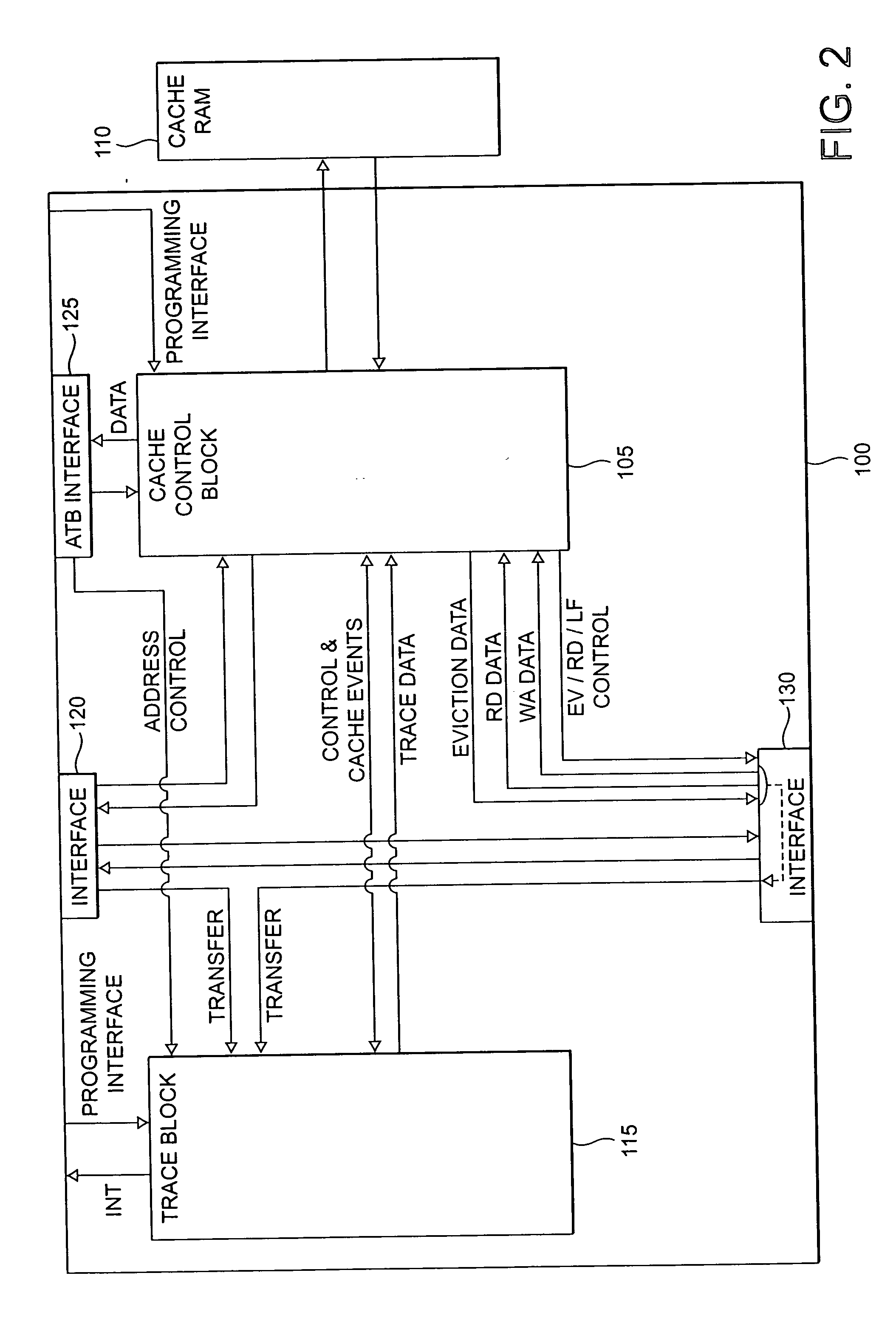
[0022] In one particular embodiment, the trace logic comprises monitor logic operable to monitor the amount of trace data stored in the cache memory and to issue said interrupt signal if the amount of trace data reaches a predetermined level. Hence, in this embodiment, the cache controller can keep track of the amount of trace data stored and cause trace data to be output when that trace data reaches a predetermined level, with the aim of ensuring that space is maintained within the cache for the storage of newly generated trace data.
[0023] In one simple implementation of such monitor logic, the monitor logic may comprise an address counter, with the interrupt signal being issued if the address counter reaches a preset value. This particular implementation can be effective, particularly in situations where the trace data is only read out of the cache via use of the interrupt signal.

Problems solved by technology

Whilst the ETM allows a great deal of trace data to be generated concerning the activities of the associated processor core (a processor core being an example of a master device), the ETM is unable to trace information about the actual transactions being routed from that processor core, or indeed from other master devices, onto the bus.
As SoC designs increase in complexity, so the complexity of the interconnecting bus network increases.
It is known to develop monitor logic to monitor a bus, but as bus designs increase in complexity, the complexity and size of the associated monitor logic increases.

Method used


Image

  • Storage of trace data within a data processing apparatus
  • Storage of trace data within a data processing apparatus
  • Storage of trace data within a data processing apparatus

Examples


Embodiment Construction

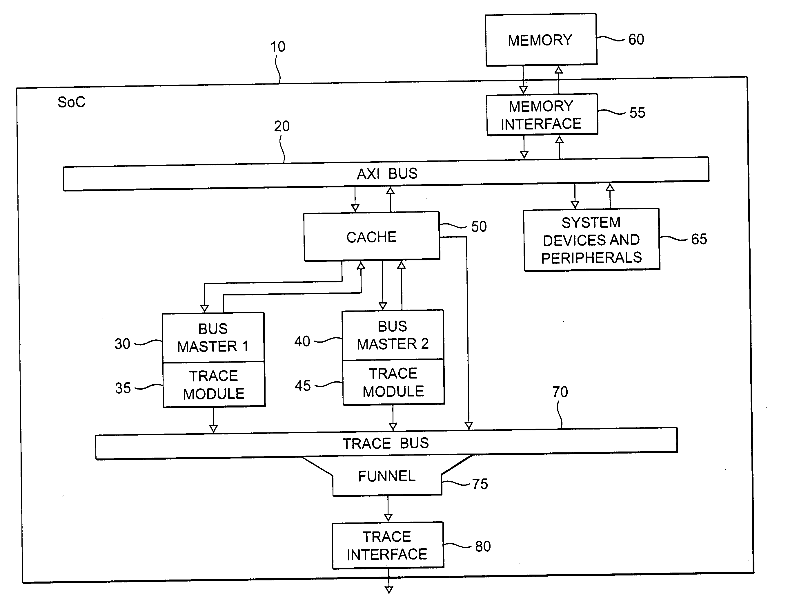
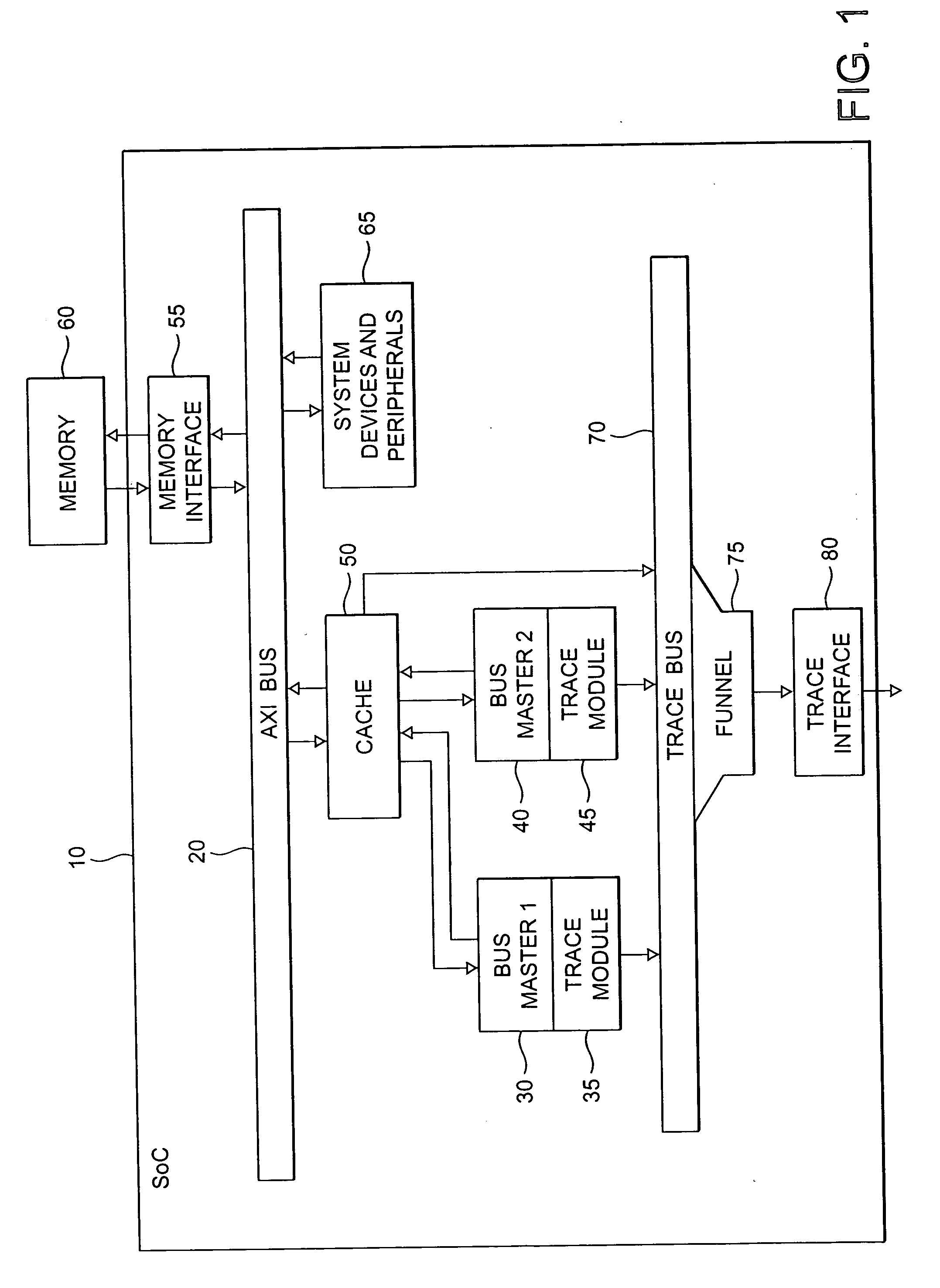
[0037]FIG. 1 is a block diagram illustrating a data processing apparatus 10 in accordance with one embodiment of the present invention. In this example, the data processing apparatus is a SoC incorporating a bus 20 having a number of master devices and slave devices coupled thereto. A master device is a device that initiates a transaction, and a slave device is a device which responds to a transaction. The bus 20 can take a variety of forms, but in FIG. 1 is assumed to be a bus conforming to the Advanced Microcontroller Bus Architecture (AMBA) AXI (Advanced extensible Interface) specification developed by ARM Limited, Cambridge, England. As shown in FIG. 1, two bus master devices 30, 40 are coupled to the bus 20 via a cache 50, such a cache often being referred to as a level 2 cache (a level 1 cache often being incorporated within the individual bus masters).

[0038] As shown in FIG. 1, the SoC 10 is connected to an external memory 60 via a memory interface 55 coupled to the bus 20, ...


PUM


Abstract

The present invention provides a data processing apparatus and method for storing trace data. The data processing apparatus comprises a bus operable to interconnect a number of master devices and slave devices to enable transactions to be routed between the master and slave devices. Each master device is able to initiate a transaction, with the transaction specifying a transaction address. A cache is interposed between at least one of the master devices and the bus and is operable to receive the transaction issued by that master device. The cache has a cache memory and a cache controller operable to control access to the cache memory. The cache controller comprises caching logic operable to selectively cache a data value of the transaction at a location in the cache memory chosen dependent on the transaction address. Control storage is provided identifying a trace address range specifying a trace region. Further, trace logic is provided which is operable to selectively generate as trace data one or more attributes associated with the transaction and to provide in association with that trace data a trace address selected from the trace address range. The caching logic is then operable to store the trace data at a location in the cache memory chosen dependent on the trace address. In this way, the cache can be used in a flexible manner to not only act as a normal cache but also to selectively store within the cache trace data.

Description

BACKGROUND OF THE INVENTION [0001] 1. Field of the Invention [0002] The present invention relates to a data processing apparatus and method for storing trace data. [0003] 2. Background of the Invention [0004] Tracing the activity of a data processing system whereby a stream of trace data is generated including data representing the step-by-step activity within the system is a highly useful tool in system development. As well as off-chip tracing mechanisms for capturing and analyzing trace data, increased amounts of tracing functionality are being placed on-chip. An example of such on-chip tracing mechanisms is the Embedded Trace Macrocell (ETM) provided by ARM Limited, Cambridge, England in association with various of their ARM processors. [0005] Such tracing mechanisms produce in real time a stream of trace elements representing activities of the data processing system that are desired to be traced. This trace stream can then subsequently be used to facilitate debugging of sequence...

Claims


Application Information

Patent Timeline
Patent Type & Authority Applications(United States)
IPC IPC(8): G06F11/00
CPCG06F11/348
Inventor MCHALE, DAVID F.VARMA, RAHOUL K.WICKS, MARC R.LIVESLEY, MIKEDUNCAN, GARETH
Owner ARM LTD
Learn More