Load based suspension motion limiting

a technology of load-based suspension and motion limitation, which is applied in the direction of mechanical machines/dredgers, trailer steering, transportation items, etc., can solve the problems of varying vertical loads on the blade and the suspended chassis of the vehicle, loose suspension, and inability to generate a full blade load

Active Publication Date: 2006-06-01
DEERE & CO
View PDF26 Cites 13 Cited by
  • Summary
  • Abstract
  • Description
  • Claims
  • Application Information

AI Technical Summary

Benefits of technology

[0010] The invention overcomes this problem by adding a standard pilot operated check valve to the rod end port of each cylinder. The pilot end of each check valve is connected to the head end of each corresponding cylinder. When the suspension is operating in a normal (weight bearing) condition, the pressure on the head end of the cylinder holds the check valve in an open position and the suspension operates normally with no affect from this valve. When the we...

Problems solved by technology

This travel produces a looseness in the suspension and does not allow a full blade load to be generated when desired.
Naturally, such a suspension system will tend to allow variations in the height of the blade above the ground as the blade encounters grea...

Method used


Image

  • Load based suspension motion limiting
  • Load based suspension motion limiting
  • Load based suspension motion limiting

Examples


Embodiment Construction

[0020] The exemplary embodiment of the invention described herein is applied to a crawler dozer with four independent track systems. In this configuration, the track systems are mounted such that they can move in a way that they can follow the contour of the ground. Each of the tracks pivots about a drive wheel.

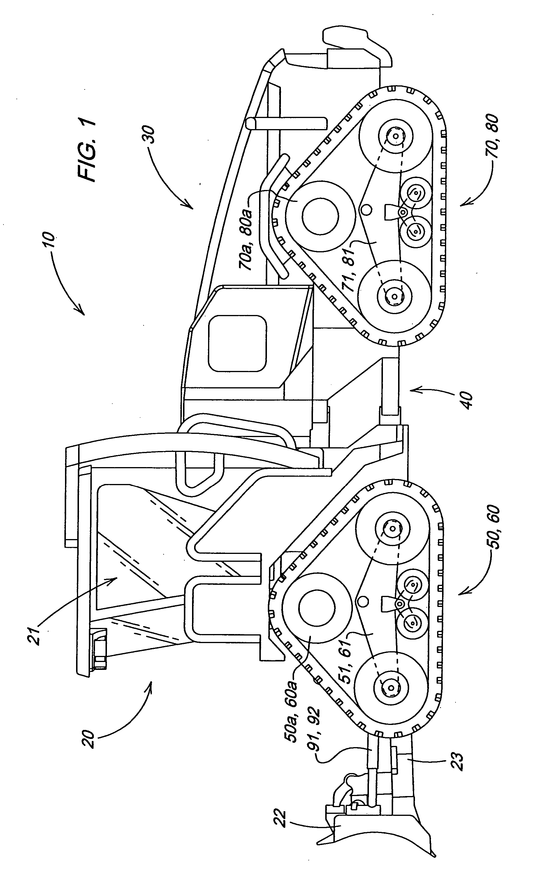
[0021]FIG. 1 illustrates a vehicle in which the invention may be used. The particular vehicle illustrated in FIG. 1 is a four track articulated dozer 10 having a front portion 20 a rear portion 30; an articulation mechanism 40 between the front portion 20 and the rear portion 30; first and second track systems 50, 60; and third and fourth track systems 70, 80. The front portion 20 includes a blade 22 and a blade mounting frame 23 as well as an operator cab 21.

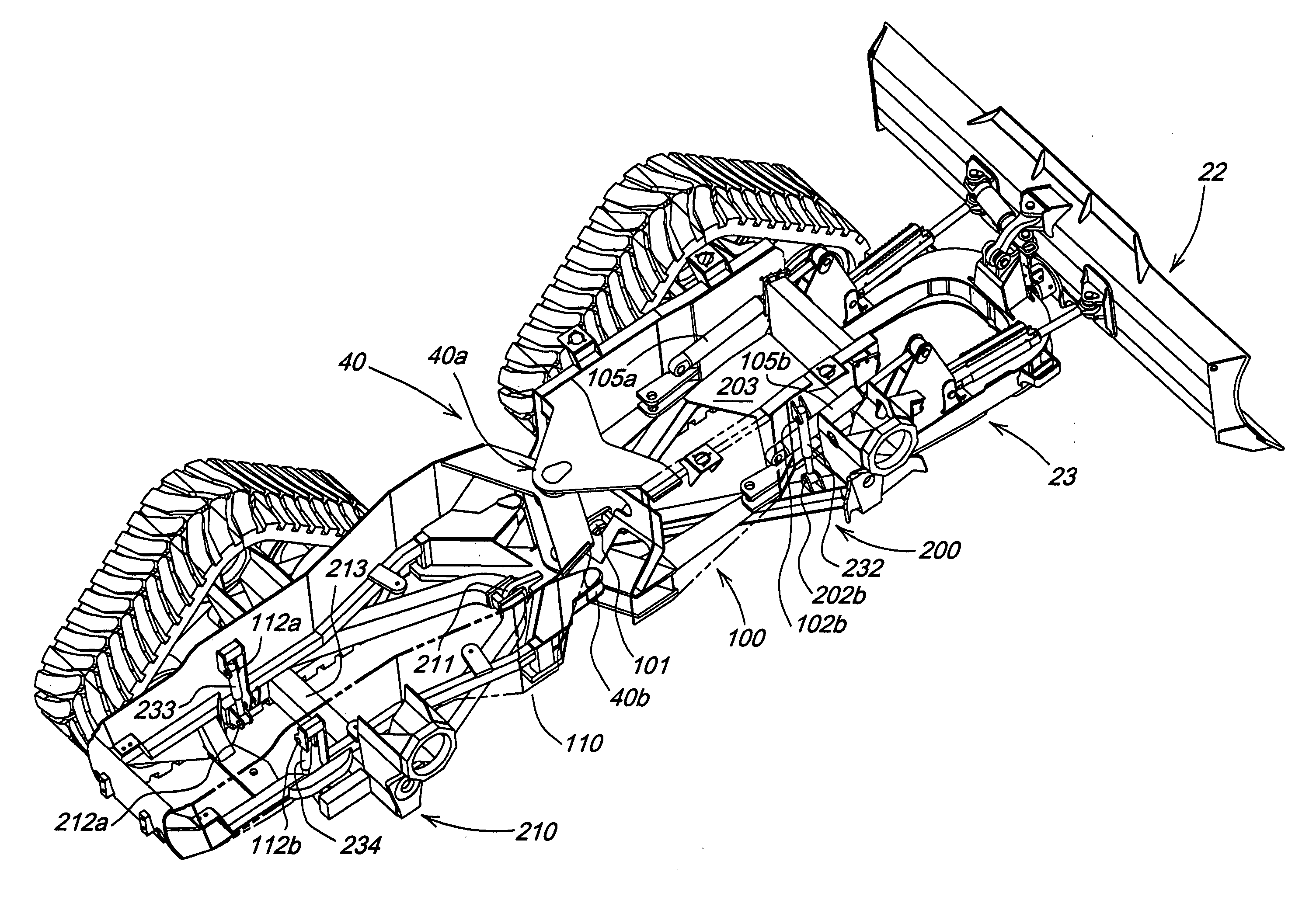
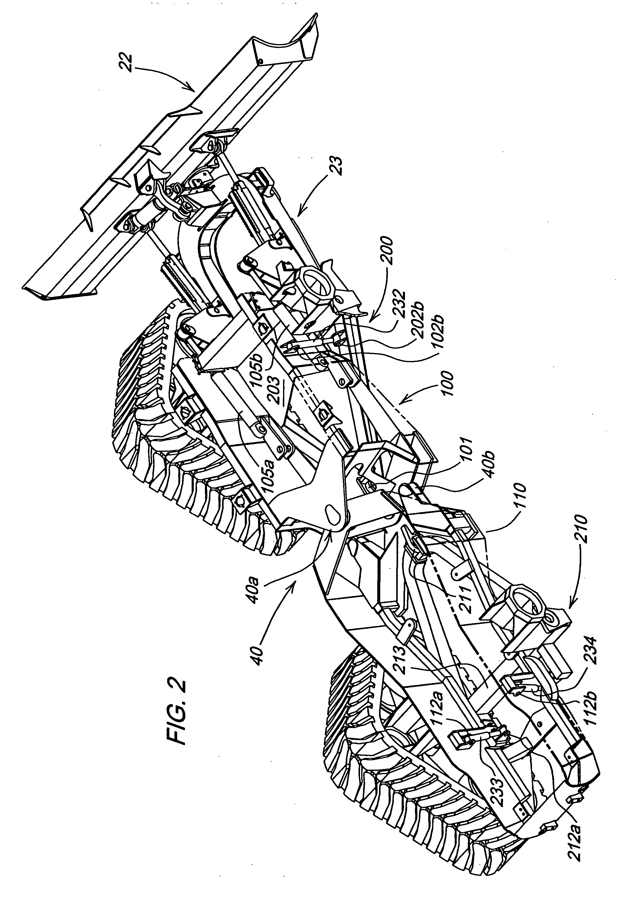
[0022] A first A-frame 200 is pivotally connected to both the first and second track systems 50, 60, i.e., rocker arms 51, 61 at first and second track frame pivots 51a, 61a. This first A-frame 200 is connected to a fr...


PUM


Abstract

An articulated loader has an articulated chassis and two A-frames. The points of the A-frames face each other. The articulated chassis includes a front portion and a rear portion. Likewise, there is a front or first A-frame and a rear or second A-frame. The A-frames are connected to the overall chassis at points close to but offset from the point of vehicle articulation via ball joints and via hydraulic suspension cylinders toward the wider portions of the “A”s. The vehicle is propelled along the ground by independently driven tracks. The invention includes a feature to limit the motion of the suspension system based on the load appied to the suspension cylinders, i.e., the pressure experienced by the head end of the suspension cylinders. This is accomplished via pilot operated check valves.

Description

FIELD OF THE INVENTION [0001] This applies to an articulated crawler dozer with an independent suspension system. BACKGROUND OF THE INVENTION [0002] conventional construction vehicles (dozers, loaders, backhoes, skid steers, graders, etc) do not usually have cushioning suspension systems but are, at most, equipped with pneumatic tires. The consequence is that the machine ride can be very harsh dependant upon the operating conditions of the machine. Presented herein is an articulated dozer with an independent suspension system that reduces the harshness of the ride. [0003] Agricultural tractors are increasingly incorporating suspension systems to reduce the shock to the vehicle and increase the operational speed of the vehicle. [0004] Traditionally, blade equipped machines such as crawlers or graders are structurally rigid. Such rigidity is desirable to prevent vertical motion of the in response to changing soil conditions. The cutting edge is typically angled back at the top so that...

Claims


Application Information

Patent Timeline
IPC IPC(8): E02F3/76B62D55/00
CPCB60G21/073B60G2300/09B60G2300/32B62D55/0655B62D55/112E02F9/0841
Inventor RADKE, DANIEL DEANNAGORCKA, JAMES ARTHURALLEN, LYAL DOUGLAS
Owner DEERE & CO
Why Eureka
Try Eureka