Vehicle using wind force

a technology of wind power and vehicle, applied in the direction of wind power motors with solar radiation, machines/engines, light oil conversion, etc., can solve the problems of increasing the consumption of fuels such as gasoline, light oil, lpg or the like, and the price of petroleum fuels will soar, so as to increase the amount of electric power, and rotate smoothly

Inactive Publication Date: 2006-06-01
KIM JAY EUNG JUNG +2
View PDF10 Cites 91 Cited by
  • Summary
  • Abstract
  • Description
  • Claims
  • Application Information

AI Technical Summary

Benefits of technology

[0010] Meanwhile, the disk type rotary gear of the wind force power system is connected to a motor, wherein the motor is disposed on the top of the roof panel of the vehicle or at a predetermined location of the top of the roof panel, electrically connected to the charger charged with electricity through a solar heat charging plate supported by the support bar and driven by solar heat, whereby the motor helps the disk type rotary gear to rotate, increasing the amount of electric power of the electric generator.
[0011] Also, the vehicle using wind force further comprises one or more ventilation tubes for ventilating the wind from the front of the vehicle to the rear of the vehicle, wherein the ventilation tubes are fixed to the body of the vehicle, wherein wind-swept place projections are formed on the disk type plate coupled to the shaft in equal distance in all directions, an outlet of each of the ventilation tubes is curved in the rotary direction of the shaft, whereby the outlet is oriented toward the wind-swept place projection and a disk type rotary gear fixed to the bottom of the shaft is made to rotate, increasing the amount of electric power of an electric generator.
[0012] Accordingly, in the vehicle using wind force, the rotary shaft rotatably fixed to the trunk lead in the rear of the vehicle and the members connected thereto can be in a no-load state by means of the maglev of the permanent magnets. Thus, as the rotary and members can smoothly rotate in a breeze, the vehicle can generate electricity. Furthermore, the rotary shaft can be more smoothly rotated by means of a streamline shape that the height of the rear of the vehicle is lower than that of the front of the vehicle, the rotary force of a small-sized motor powered by solar energy, the rotary force depending on the relative motion between the permanent magnets, and transfer of the wind of the ventilation tube that is penetrated from the front of the vehicle to the rear of the vehicle. Thereby, the amount of electricity greater than needed to drive the vehicle can be generated.

Problems solved by technology

As the number of vehicles is increased, the amount of consumption of fuels such as gasoline, light oil, LPG or the like is further increased.
It is expected that those fuels will be depleted in the near future.
Accordingly, as time goes, the price of the petroleum fuels soars.
Further, smoke, etc. generated when the petroleum fuels are combusted becomes a factor that causes severe environmental contamination.
The vehicle using electricity cannot be charged while being driven and requires a long time to charge electricity.
Furthermore, in order to install an electricity charging station, an expensive electric power cable has to be extended to the electricity charging station.
In this case, not only its installation cost is very high, but also the facilities are very dangerous.
In this connection, the electric vehicle is applied to only leisure or carts for a golf course, but is not commercialized.

Method used


Image

  • Vehicle using wind force
  • Vehicle using wind force
  • Vehicle using wind force

Examples


first embodiment

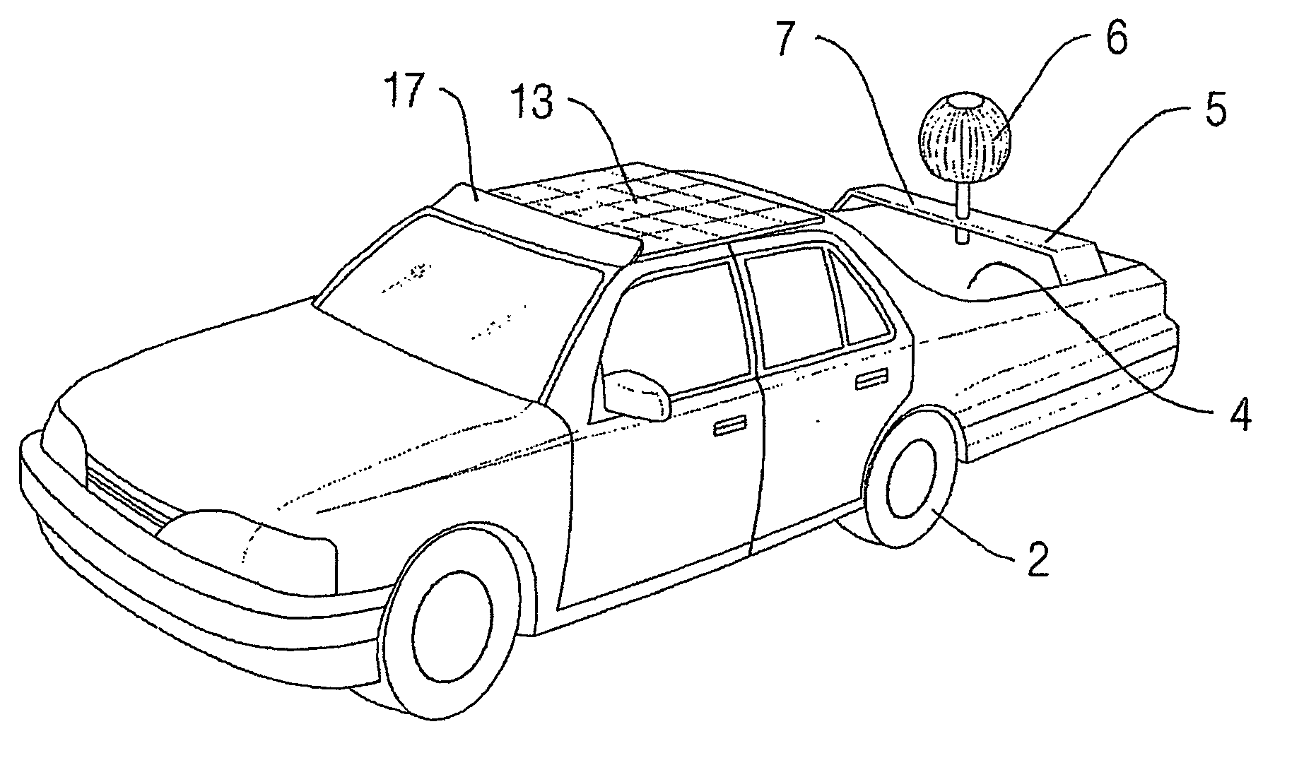
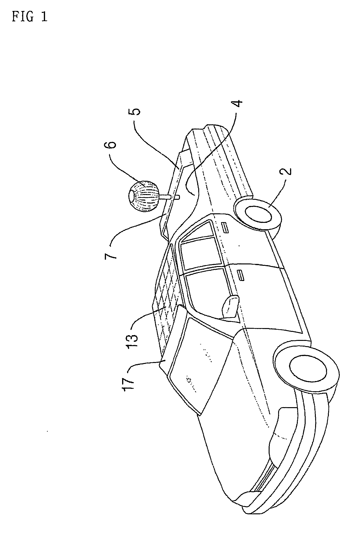
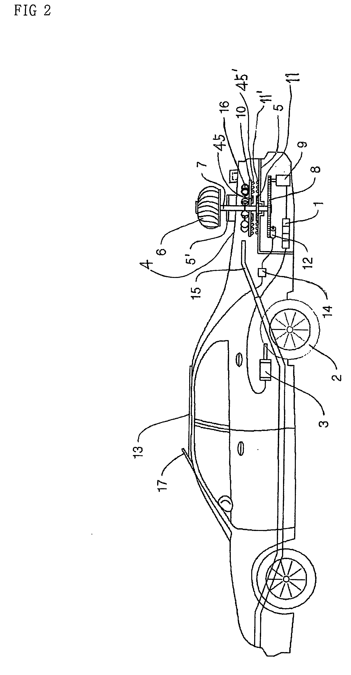
[0021] Referring to FIG. 1 and FIG. 2, a driving motor 3 is electrically connected to a battery 1 and connected to a driving wheel 2. The driving motor 3 transfers rotary force of the driving wheel 2 to the driving wheel 2. In this case, the rear of a vehicle provided with the driving motor 3 is formed lower than its front in a streamline shape so that wind can move toward the rear of the vehicle on wind.

[0022] Supports 5 and 5′ are each disposed in and out of a trunk lead 4 of the vehicle. A spherical ventilator 6 is formed in the outside support 5′, so that ventilator 6 is rotated by wind. A disk type plate type gear 8 is fixed to the bottom of a shaft 7 connected to the ventilator 6. In the above, the gear 8 is engaged with the shaft of an electric generator 9, so that electricity generated therefrom is charged to the battery 1. A disk type plate 10 is fixed on the shaft 7. Pairs of permanent magnets 11, 11′, 45 and 45′ are each formed on the opposite side of each of the inside ...

second embodiment

[0036] Meanwhile, in addition to the wind force power system formed in the truck lead 4 in the rear of the vehicle as described above, a wind force power system 20 is added to the hood panel at the front of the vehicle in order to double the generating power, as shown in FIG. 3 and FIG. 4.

[0037] In other words, an intercooler 112 is formed at the hood panel in the rear of the vehicle. The wind force power system 20 is formed within the intercooler 112, i.e., the hood panel.

[0038] The wind force power system 20 includes a ventilator 22 for rotating the air introduced through the intercooler 112 formed at the hood panel in the front of the vehicle, a rotary gear 32 connected to the ventilator 22 and the shaft 24, a follower gear 36 engaged with the rotary gear 32 to cooperatively operate with the gear 32, and an electric generator 34 connected to the follower gear 36.

[0039] Meanwhile, a disk type plate 25 cooperatively operated with the shaft 24 is disposed in the center of the sha...


PUM


Abstract

Disclosed is a vehicle using wind force. An object of the present invention is to provide a wind force power system driven by wind is provided within a hood panel of the vehicle, whereby the vehicle continuously charge a battery with electricity while being stopped or driving. The vehicle using wind force includes a wind force power system, the Power system comprising a ventilator that is rotated by the wind flowing along the roof panel in the rear of the vehicle, a shaft connected to the ventilator, a rotary gear connected to the shaft, a follower gear engaged with the rotary gear, and an electric generator for generating electricity as the follower gear rotates, wherein the electric generator of the wind force power system is electrically connected to the battery and the battery is electrically connected to the driving motor.

Description

TECHNICAL FIELD [0001] The present invention relates to a vehicle using wind force. More particularly, the present invention relates to a vehicle using wind force in which a wind force isolated power system driven by wind is provided in a trunk lead at the rear of the vehicle and a hood panel at the front of the vehicle, respectively, whereby the vehicle continuously generates electricity while being stopped or driving, thus charging a battery. BACKGROUND ART [0002] As noted well, because of convenience and rapidity of long distance traveling, the number of vehicle holdings every home is increased. In Korea, the number of vehicle holdings exceeds 10 millions. On average, each home holds one or more vehicles. [0003] As the number of vehicles is increased, the amount of consumption of fuels such as gasoline, light oil, LPG or the like is further increased. Such petroleum fuels have the estimated amount of deposits. It is expected that those fuels will be depleted in the near future. [...

Claims


Application Information

Patent Timeline
Patent Type & Authority Applications(United States)
IPC IPC(8): B60K16/00B60L8/00F03D11/04
CPCB60K16/00B60K2016/003B60K2016/006B60L8/003B60L8/006F03D9/002F03D11/04F05B2240/215F05B2240/91F05B2240/941Y02E10/725Y02E10/728Y02T10/7083Y02T10/90F03D13/20F03D9/25F03D9/32F03D9/007F03D15/00H02S10/12Y02E10/50Y02E10/72Y02T10/7072
Inventor KIM, KWANG SIK
Owner KIM JAY EUNG JUNG
Why Eureka
Try Eureka