Eureka AIR delivers breakthrough ideas for toughest innovation challenges, trusted by R&D personnel around the world.

Device and method of classifying emulsion and method of demulsifying emulsion

a technology of emulsion and liquid, which is applied in the direction of moving filter element filters, filtration separation, separation processes, etc., can solve the problems of inability to classify liquid droplets passing through the filter, long time to separate the emulsion into two liquids, and may keep the emulsion stable for a long tim

Inactive Publication Date: 2006-06-01
SUMITOMO CHEM CO LTD
View PDF23 Cites 5 Cited by
  • Summary
  • Abstract
  • Description
  • Claims
  • Application Information

AI Technical Summary

Benefits of technology

[0021] The present invention has been attained in view of the above problems, and an object thereof is to provide a classifying apparatus and a classifying method for more easily classifying liquid droplets contained in an emulsion to obtain liquid droplets having a desired diameter or smaller.
[0025] That is, with the above arrangement, it is possible to reliably flow the liquid droplets contained in the emulsion through the flow path having the smallest length. Thus, it is possible to classify the liquid droplets contained in the emulsion so as to obtain liquid droplets having a desired diameter or smaller.
[0028] That is, with the above arrangement, it is possible to reliably flow the liquid droplets contained in the emulsion through the flow path having the smallest length. Therefore, the liquid droplets larger than the smallest length can coalesce with each other to form a continuous phase, and then separate from the emulsion. Thus, it is possible to classify the liquid droplets contained in the emulsion so as to obtain liquid droplets having a desired diameter or smaller.
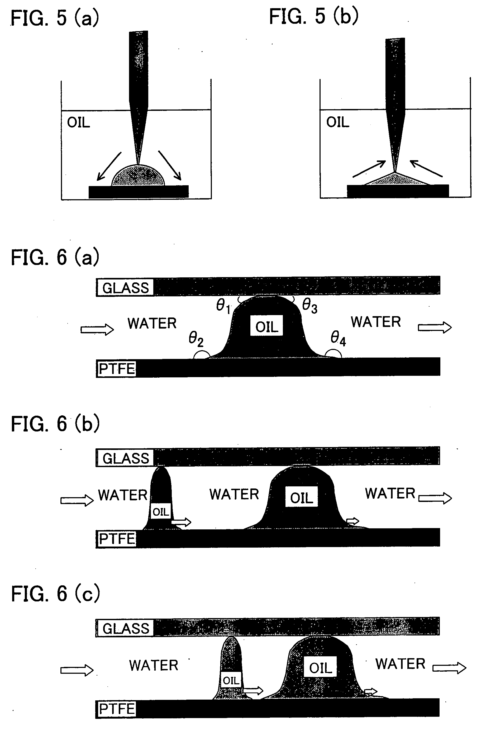
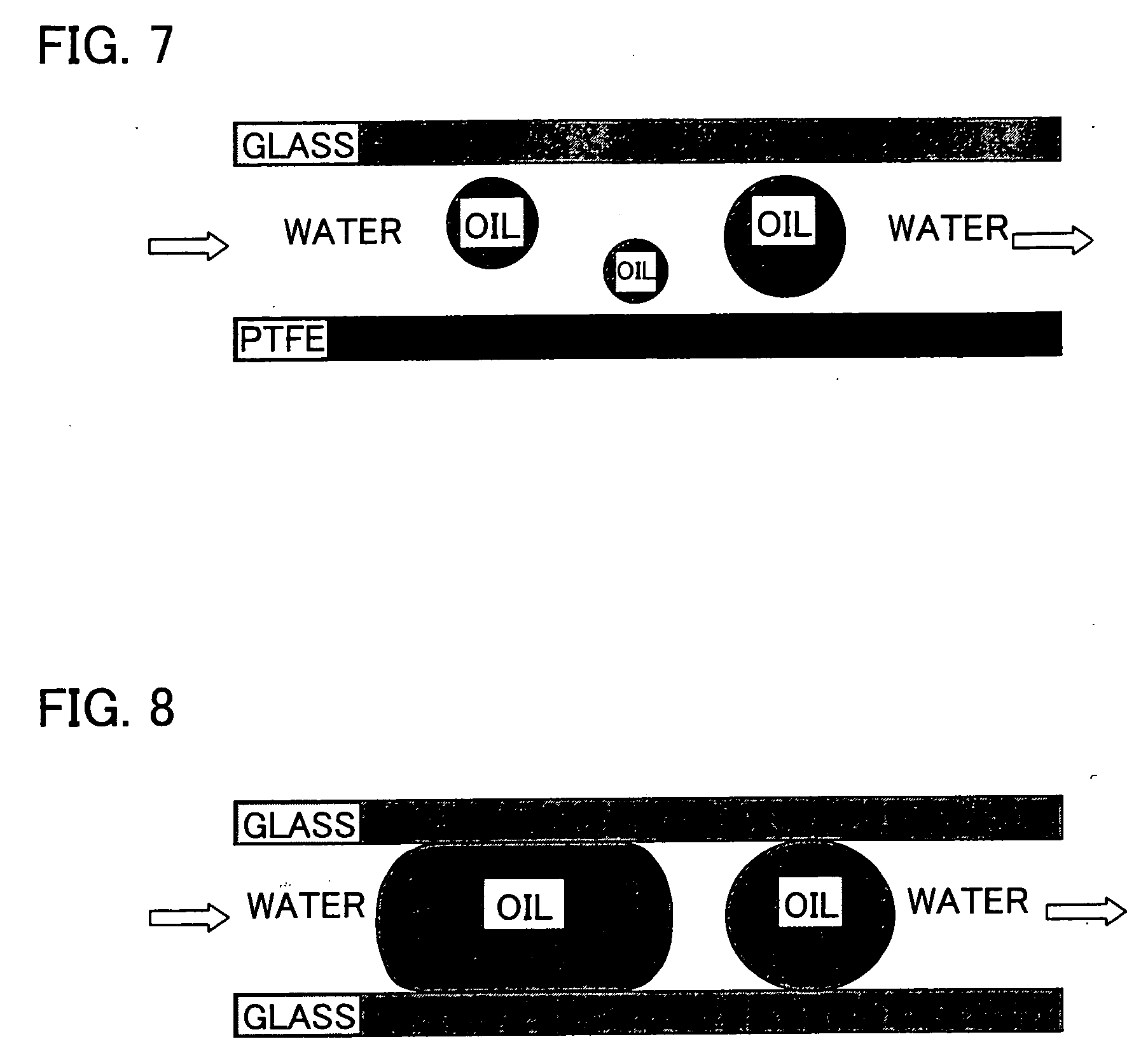
[0030] According to the above arrangement, the liquid droplets larger than the smallest length can be formed to a larger liquid droplet (made coalesced with each other) in such a manner that the liquid droplets contained in the emulsion are caused to pass through the flow path having the smallest length, more specifically, the liquid droplets contained in the emulsion are caused to pass in a wetted state through the flow path. Thus, it is possible to easily phase-separate the emulsion for demulsification.

Problems solved by technology

Therefore, these emulsions may keep stable for a long time.
Thus, when such a stable emulsion is used, i.e. when demulsification is not readily performed, it takes long time to separate the emulsion into two liquids even though the extraction is performed promptly.
Thus, the arrangement of the patent document 1 cannot adjust opening diameters of the flow path through which liquid droplets contained in the emulsion pass in the filter to make uniform opening diameters, thus making impossible to classify liquid droplets passing though the filter so as to obtain droplets having a desired diameter or smaller.
Further, the arrangements disclosed in the patent documents 1 and 2 cannot adjust the flow path of liquid droplets contained in the emulsion.
Still further, the arrangements disclosed in the patent documents 1 and 2 cannot provide uniform opening diameters of the filter grains.
In addition, it becomes more difficult to make a uniform distribution of the opening diameters as the opening diameter of the filter grains becomes smaller.
For example, it is very difficult to classify an emulsion having extremely-small-diameter liquid droplets generated with the use of the micromixer disclosed in the non-patent document 2.
Besides, in a case where the filters disclosed in the patent documents 1 and 2 are used, the filters gradually swell due to a long-time separation into oil and water.
Thus, it is very difficult for the filters to provide a constant oil-and-water separation performance all the time.

Method used


Image

  • Device and method of classifying emulsion and method of demulsifying emulsion
  • Device and method of classifying emulsion and method of demulsifying emulsion
  • Device and method of classifying emulsion and method of demulsifying emulsion

Examples


example 1

[0161] For production of an emulsion, water and dodecane were supplied to a micromixer (produced by IMM GmbH; single mixer) at rates of 2.7 ml / min and 0.3 ml / min, respectively. Then, diameters of liquid droplets contained in a just-produced emulsion were measured by means of the laser diffraction / scattering particle size distribution analyzer (HORIBA LA-920).

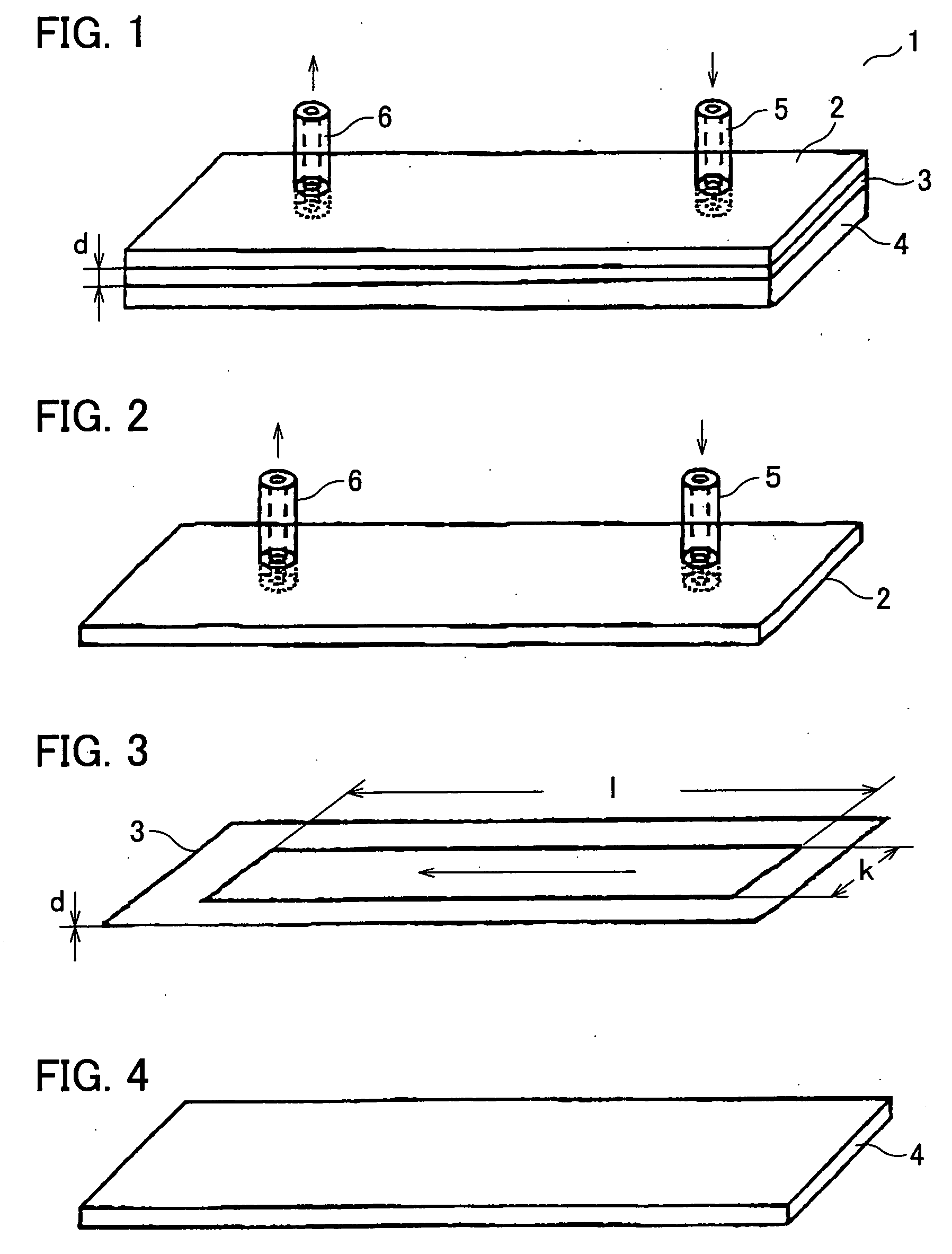
[0162] Next, an outlet of the micromixer was connected to the supply port 5 of the classifying apparatus including the upper plate 2 made of glass and the lower plate 4 made of PE, and the emulsion was supplied to the classifying apparatus at a rate of 3 ml / min. Then, liquids discharged out of the exit 6 of the classifying apparatus were stored in a measuring cylinder (7 mm in diameter). Of generated aqueous phase part and oil phase part, the aqueous phase part was observed. If the aqueous phase part was clouded, failure of demulsification of the emulsion is indicated with x. On the other hand, if the aqueous phase part was cle...

example 2

[0163] Except for the use of a classifying apparatus including the upper plate 2 made of glass and the lower plate 4 made of PP, obtained liquids were observed as in Example 1. Observation results are shown in Table 1.

example 3

[0164] Except for the use of a classifying apparatus including the upper plate 2 made of glass and the lower plate 4 made of PTFE, obtained liquids were observed as in Example 1. Observation results are shown in Table 1.


PUM

PropertyMeasurementUnit
dynamic contact angleaaaaaaaaaa
residence timeaaaaaaaaaa
diameteraaaaaaaaaa

Abstract

A classifying apparatus (1) has a flow path (structure) through which an emulsion flows. The flow path is provided between at least two plates (upper plate (2), lower plate (4)) that are separated by a distance smaller than the largest diameter of a liquid droplet included in the emulsion. Emulsion is fed from a supply port (5) provided in the upper plate (2) and can be classified by passing it in the flow path.

Description

TECHNICAL FIELD [0001] The present invention relates to a classifying apparatus and a classifying method of obtaining only tiny liquid droplets by an emulsion classification performed in such a manner that large liquid particles (liquid droplets) in an emulsion containing liquid droplets with different particle diameters (droplet diameters) are made coalesced with each other. More specifically, the present invention relates to a classifying apparatus and a classifying method capable of demulsifying liquid droplets to a continuous phase by classifying the emulsion to obtain liquid droplets having so small diameter that cannot be visually observed. BACKGROUND ART [0002] A liquid-liquid extraction performed in such a manner that after a useful substance dissolved in an aqueous phase is extracted to an oil phase, or after a salt and other substance dissolved in an oil phase is extracted to an aqueous phase, the useful substance and the salt are extracted by separation into the aqueous p...

Claims


Application Information

Patent Timeline
Patent Type & Authority Applications(United States)
IPC IPC(8): B01D29/00B01D24/00B01D17/04B03B
CPCB01D17/045B01D17/04
Inventor OKUBO, YOSHIHITOMAKI, TAISUKETOMA, MASAAKIMAE, KAZUHIRO
Owner SUMITOMO CHEM CO LTD
Why Eureka
Eureka Blog
Learn More