Printing screen, printing process and method for improving side-bottom ratio

a printing process and side-bottom ratio technology, applied in the manufacture of electrode systems, electric discharge tubes/lamps, discharge tube coatings, etc., can solve the problem of downgraded improve the side-bottom ratio of fluorescent layers, and enhance the luminescent efficiency of plasma display apparatuses.

Active Publication Date: 2006-06-01
CPT TECH GRP
View PDF1 Cites 2 Cited by
  • Summary
  • Abstract
  • Description
  • Claims
  • Application Information

AI Technical Summary

Benefits of technology

[0019] To sum up, the present invention, the printing screen, the printing process and the method for improving side-bottom ratio, can be applied in a printing process of the fluorescent laye...

Problems solved by technology

Consequently, the luminescent efficiency ...

Method used


Image

  • Printing screen, printing process and method for improving side-bottom ratio
  • Printing screen, printing process and method for improving side-bottom ratio
  • Printing screen, printing process and method for improving side-bottom ratio

Examples


Embodiment Construction

[0027] Various specific embodiments of the present invention are disclosed below, illustrating examples of various possible implementations of the concepts of the present invention. The following description is made for the purpose of illustrating the general principles of the invention and should not be taken in a limiting sense. The scope of the invention is best determined by reference to the appended claims.

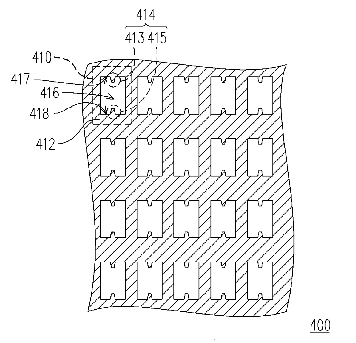
[0028] The present invention provides a printing screen with protrusions in the ink apertures. The printing screen with protrusions enables the ink liquids to flow in different speeds to the same ink aperture. Therefore, the gas in the discharge chambers can be emitted from where the ink liquid flows in a slower speed, so as to avoid the uneven thickness of the fluorescent layer due to the gas enveloped in the ink liquids in the discharge chamber.

[0029]FIG. 4 is a top view of a printing screen according to one embodiment of the present invention. As shown in FIG. 4, a print...


PUM


Abstract

A printing screen, printing process and method for improving side-bottom ratio are provided. The printing screen mainly comprises a plurality of printing units, wherein each of the printing units comprises a body and a protrusion structure. The body has an ink aperture, and the protrusion structure extends from a surface of the body into the ink aperture. The printing process of a fluorescent layer in a plasma display panel utilizing the said printing screen can enhance the uneven film thickness of the fluorescent layer on the bottom of a discharge chamber, and further improve the side-bottom ratio of the fluorescent layer in a plasma display panel.

Description

BACKGROUND OF THE INVENTION [0001] 1. Field of the Invention [0002] The present invention relates to a printing screen and a printing process using the same. More particularly, the present invention relates to a method for improving a side-bottom ratio of a fluorescent layer in a plasma display panel and the printing screen used. [0003] 2. Description of Related Art [0004] In recent years, with the rapid advancement of microelectronics technology, the information, communication, network technology and the relative industry have also developed. With that trend, the display apparatus, showing words, data, pictures and moving images, has become an indispensable element. Wherein, the plasma display apparatus, with its advantages such as big size, self-luminescence, wide view angle, thinness and full colors, has a great potential of becoming the mainstream flat panel display apparatus in its next generation. [0005]FIG. 1 is a three-dimensional view of a decomposed conventional plasma dis...

Claims


Application Information

Patent Timeline
IPC IPC(8): H01J17/49H01J29/10
CPCH01J9/227H01J2209/012H01J2211/42
Inventor CHUEH, CHUANG-CHUNLEE, SU-CHIU
Owner CPT TECH GRP
Why Eureka
Try Eureka