Supercharge Your Innovation With Domain-Expert AI Agents!

Synchronous moter driving apparatus

a technology of synchronous motors and driving apparatuses, which is applied in the direction of motor/generator/converter stoppers, electronic commutators, dynamo-electric converter control, etc., can solve the problems of not always achieving sufficient magnetic saturation and sometimes not standing up, and achieve high accuracy and high accuracy

Active Publication Date: 2006-06-01
HITACHI IND EQUIP SYST CO LTD
View PDF3 Cites 13 Cited by
  • Summary
  • Abstract
  • Description
  • Claims
  • Application Information

AI Technical Summary

Benefits of technology

[0006] It is an object of the present invention to provide a synchronous motor driving apparatus which can presume a magnetic pole position of a synchronous motor with high accuracy without influence exerted by difference in structure of the synchronous motor.
[0007] It is another object of the present invention to provide a synchronous motor driving apparatus which can presume a magnetic pole position of a synchronous motor with high accuracy irrespective of structure of the synchronous motor by using only DC current of a power converter for driving the synchronous motor.
[0010] According to the present invention, there can be provided the synchronous motor driving apparatus which can presume the magnetic pole position of the synchronous motor with high accuracy without influence exerted by difference in structure of the synchronous motor.

Problems solved by technology

However, in fact, the supposition does not sometimes necessarily stand up according to the magnitude of the current Idc due to the rotor structure, the stator slot structure, the winding method and the like of the PM motor.
The influence thereof can be solved by increasing the amplitude of the voltage pulse and enhancing the magnetic saturation, although it is restricted by a controller for driving the motor and sufficient magnetic saturation is not necessarily obtained.

Method used


Image

  • Synchronous moter driving apparatus
  • Synchronous moter driving apparatus
  • Synchronous moter driving apparatus

Examples


embodiment 2

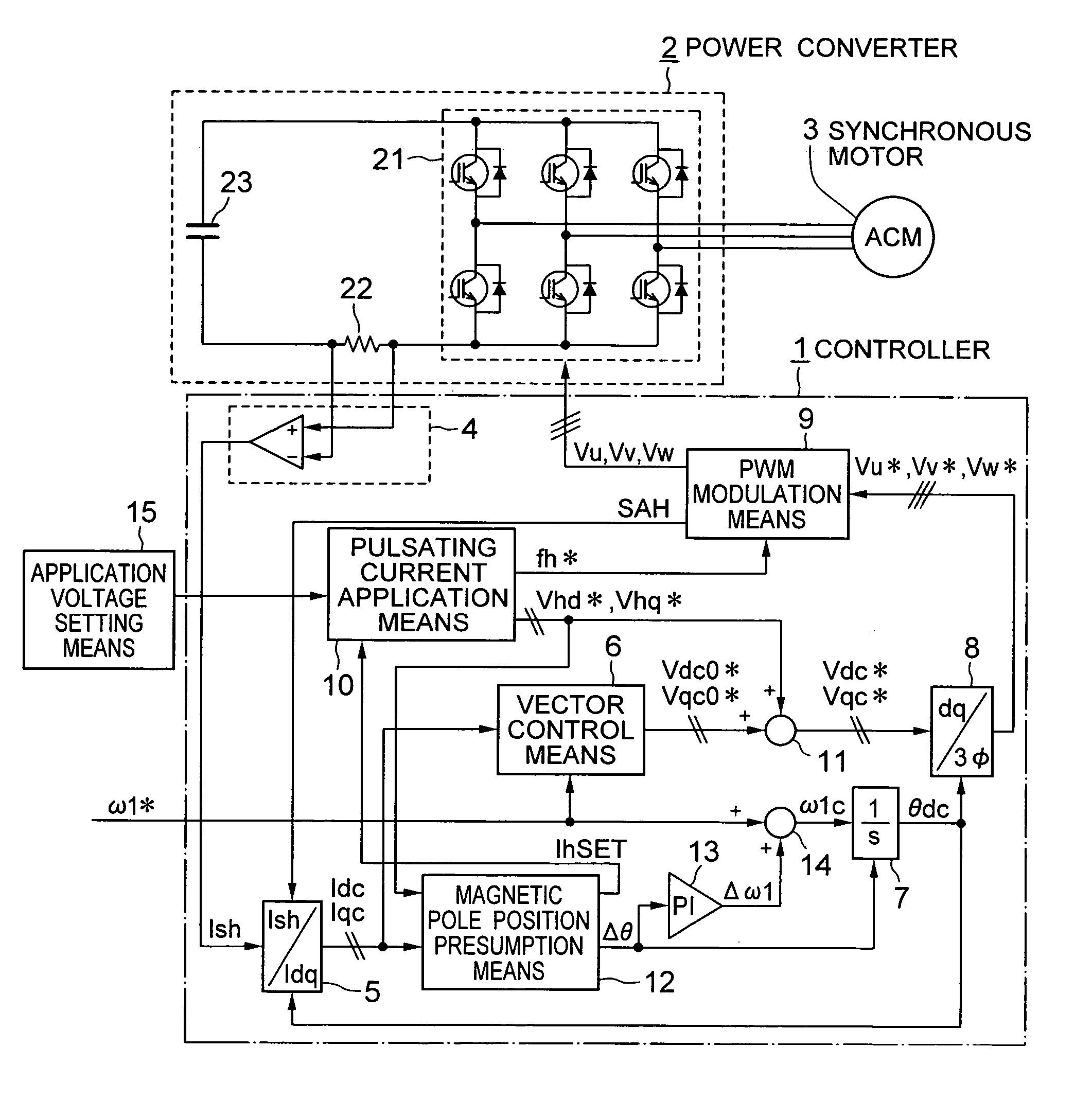
[0082] A second embodiment of the present invention is now described. The whole system configuration of the embodiment is the same as that of the first embodiment shown in FIG. 1 and the generation method of the phase output voltage commands Vu, Vv and Vw and operation of the magnetic pole position presumption means 12 of the embodiment are different from those of the first embodiment.

[0083]FIG. 10 shows operation waveforms in the embodiment in case where the signal voltage command is applied to only the dc-axis (Vhq*=0) and FIG. 11 shows operation waveforms in the embodiment in case where the signal voltage command is applied to only the qc-axis (Vhd*=0).

[0084]FIG. 10(a) shows a waveform of Vhd*. A triangular wave shown in FIG. 10(b) is a triangular wave carrier for the pulse width modulation. In the embodiment, it is supposed that Vhd* is a square wave having a period equal to four times as long as that of the triangular wave carrier and the operation period of the control syste...

embodiment 3

[0095] A third embodiment of the present invention is now described. The system configuration thereof is the same as that of the first embodiment shown in FIG. 1 and the generation method of the phase output voltage commands Vu, Vv and Vw and operation of the magnetic pole position presumption means 12 in the embodiment are different from those of the first embodiment.

[0096]FIG. 16 shows operation waveforms in the embodiment in case where the signal voltage command is applied to only the dc-axis (Vhq*=0) and FIG. 17 shows operation waveforms in the embodiment in case where the signal voltage command is applied to only the qc-axis (Vhd*=0).

[0097] In the embodiment, the pulse width modulation frequency f-PWM is changed on the basis of the phase voltage commands Vu*, Vv* and Vw* so that change in voltage between two phases between which the line voltage is maximum is equal to the voltage of the DC voltage supply 23. Further, the phase voltage commands are prepared so that a changed w...

embodiment 4

[0106] A fourth embodiment of the present invention is now described. The system configuration thereof is the same as that of the first embodiment shown in FIG. 1. The generation method of the phase output voltage commands Vu, Vv and Vw and operation of the magnetic pole position presumption means 12 in the embodiment are different from those of the first embodiment.

[0107]FIG. 20 shows operation waveforms in the embodiment in case where the signal voltage command is applied to only the dc-axis (Vhd*=0) and FIG. 21 shows operation waveforms in the embodiment in case where the signal voltage command is applied to only the qc-axis (Vhd*=0). In the embodiment, the magnetic pole position presumption operation is performed in two parts as shown in FIGS. 20 and 21 and two square wave voltages having different amplitudes are successively supplied as the application voltage commands Vhd* and Vhq*. In other words, as shown in FIG. 20(b), when the signal voltage command is applied to the dc-a...


PUM


Abstract

A synchronous motor driving apparatus having a power converter which applies AC variable voltages having variable frequency to a synchronous motor includes a pulsating current application unit for applying pulsating current to the synchronous motor and a magnetic pole position presumption unit. The magnetic pole position presumption unit detects two current values ΔIdcp1 and ΔIdcp2 on the positive side and two current values ΔIdcn1 and ΔIdcn2 on the negative side of the pulsating current and presumes the magnetic pole position of the synchronous motor on the basis of difference between change rates of ΔIdcp1→ΔIdcp2 and ΔIdcp1→ΔIdcp2.

Description

BACKGROUND OF THE INVENTION [0001] The present invention relates to a synchronous motor driving apparatus which controls a synchronous motor without using a sensor for detecting an electrical angle position. [0002] There are proposed a lot of methods of presuming an internal magnetic pole position of a synchronous motor to control the synchronous motor without detecting an electrical angle position of a rotor. For example, Japanese Patent Publication JP-A-2002-78392 discloses that voltage pulses are applied to a permanent-magnet synchronous motor (hereinafter referred to as PM motor) in two orthogonal-axis directions to detect amplitudes of current pulses generated in the respective axial directions and presume a magnetic pole position. In this method, an approximation equation showing the relation between the generated currents and the presumed magnetic pole position is introduced to thereby minimize the number of times of application of the voltage pulses, so that the accuracy of ...

Claims


Application Information

Patent Timeline
Patent Type & Authority Applications(United States)
IPC IPC(8): H02P1/46H02P6/08H02P6/16H02P6/06H02P6/17H02P6/28
CPCH02P6/18H02P21/146H02P2203/01H02P2207/05H02P21/18
Inventor KANEKO, DAIGOIWAJI, YOSHITAKASAKAMOTO, KIYOSHIENDO, TSUNEHIROOKUBO, TOMOFUMI
Owner HITACHI IND EQUIP SYST CO LTD
Features
  • R&D
  • Intellectual Property
  • Life Sciences
  • Materials
  • Tech Scout
  • Unparalleled Data Quality
  • Higher Quality Content
  • 60% Fewer Hallucinations
Learn More