
Offset cancellation in a switching amplifier

Active Publication Date: 2006-06-01
CIRRUS LOGIC INC
View PDF20 Cites 6 Cited by
  • Summary
  • Abstract
  • Description
  • Claims
  • Application Information

AI Technical Summary

Benefits of technology

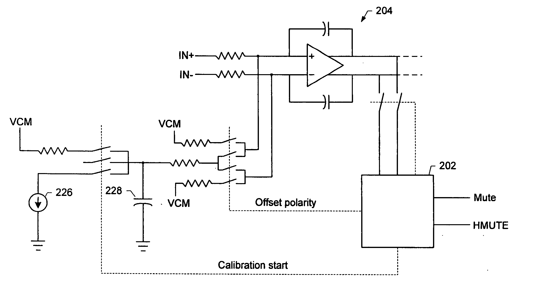
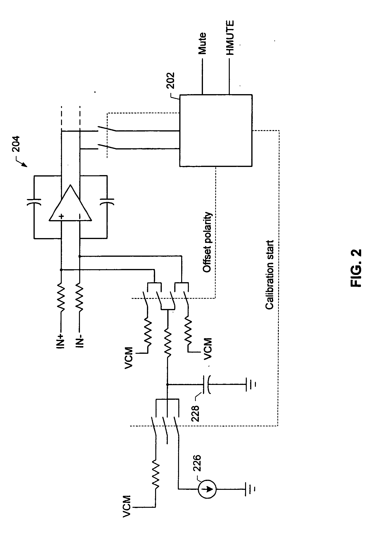
[0006] According to another embodiment, a switching circuit includes an input stage having an input referred offset voltage associated therewith. An output stage has an output offset voltage associated therewith which is due at least in part to the input referred offset associated with the input stage. Offset cancellation circuitry includes an offset calibration capacitor and control circuitry which is operable before switching of the output stage is enabled to connect the offset calibration capacitor to an input terminal of the input stage, to charge the offset calibration capacitor to a predetermined voltage, and to facilitate discharging of the offset calibration capacitor until a portion of the input referred offset voltage associated with the input stage is canceled which results in cancellation of the portion of the output offset voltage after switching of the output stage begins. The control circuitry is further operable to disconnect the offset calibration capacitor from the input terminal after switching of the output stage begins thereby allowing the output offset voltage to drift.

Problems solved by technology

Offset cancellation circuitry is operable to cancel a portion of the input referred offset voltage before switching of the output stage is enabled thereby resulting in cancellation of the portion of the output offset voltage after switching of the output stage begins.

Method used


Image

  • Offset cancellation in a switching amplifier
  • Offset cancellation in a switching amplifier
  • Offset cancellation in a switching amplifier

Examples


Embodiment Construction

[0012] Reference will now be made in detail to specific embodiments of the invention including the best modes contemplated by the inventors for carrying out the invention. Examples of these specific embodiments are illustrated in the accompanying drawings. While the invention is described in conjunction with these specific embodiments, it will be understood that it is not intended to limit the invention to the described embodiments. On the contrary, it is intended to cover alternatives, modifications, and equivalents as may be included within the spirit and scope of the invention as defined by the appended claims. In the following description, specific details are set forth in order to provide a thorough understanding of the present invention. The present invention may be practiced without some or all of these specific details. In addition, well known features may not have been described in detail to avoid unnecessarily obscuring the invention.

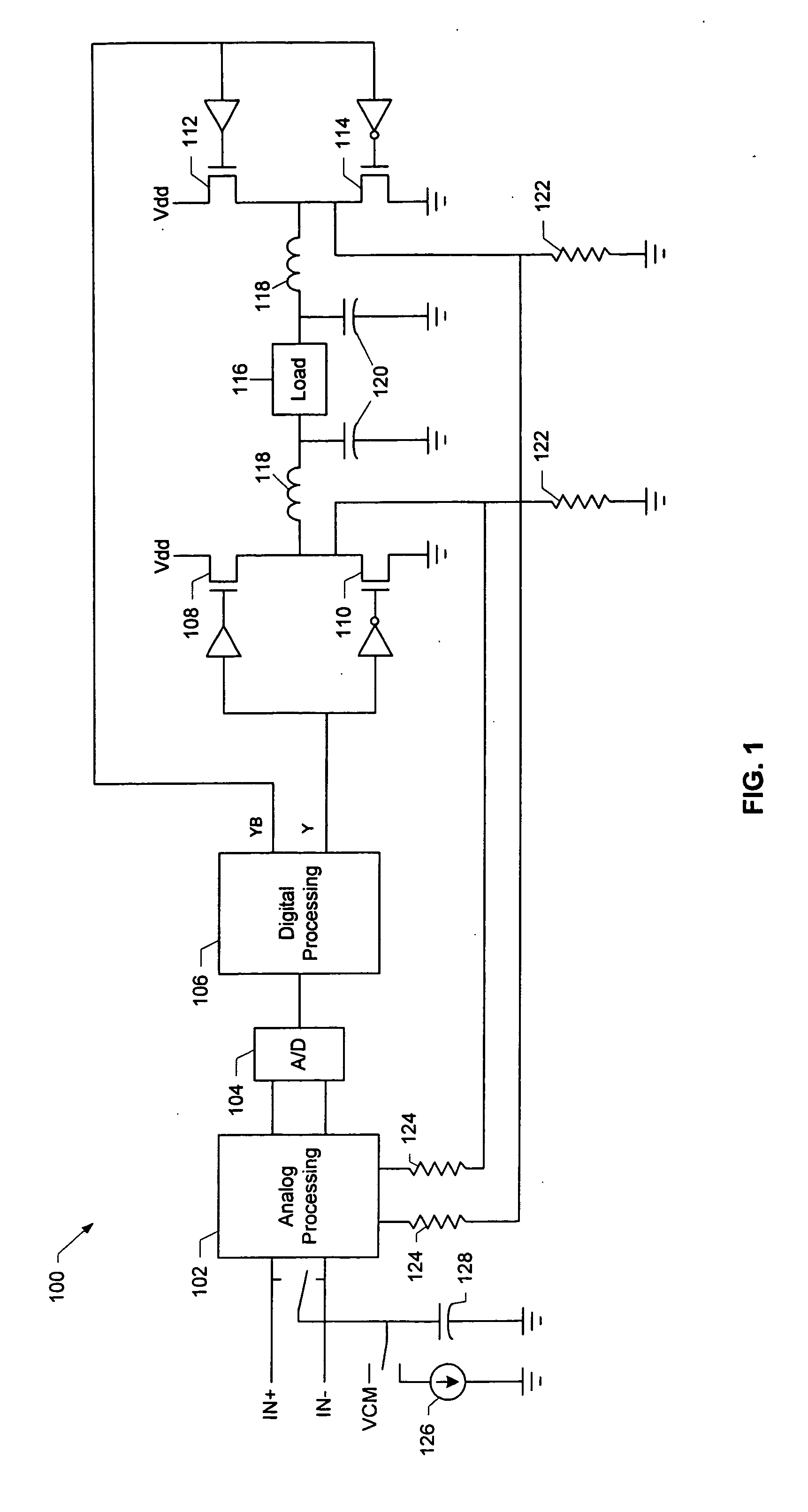
[0013]FIG. 1 is a simplified schematic...


PUM


Abstract

A switching circuit is described having an input stage having an input referred offset voltage associated therewith. An output stage has an output offset voltage associated therewith which is due at least in part to the input referred offset associated with the input stage. Offset cancellation circuitry is operable to cancel a portion of the input referred offset voltage before switching of the output stage is enabled thereby resulting in cancellation of the portion of the output offset voltage after switching of the output stage begins. The offset cancellation circuitry is further operable to release the input referred offset voltage after switching of the output stage begins thereby allowing the output offset voltage to drift.

Description

BACKGROUND OF THE INVENTION [0001] The present invention relates to switching amplifier and regulator architectures, and more specifically reducing DC offset voltages in such architectures. [0002] In virtually any amplification system, a standard design goal is the minimization of DC offset voltage. DC offset voltage is defined as a non-zero DC voltage observed at the amplifier output when zero DC voltage is applied to the input. In an audio amplifier, the DC offset voltage can appear suddenly at the output terminals (and thus at the speakers) at the instant the amplifier is energized or activated, producing an unpleasant thump or pop. This phenomenon is observed in both linear and switching (class-D) amplifiers and comes from a variety of sources. [0003] Minimization of DC offset voltage can be achieved by the use of carefully matched circuit elements, by adaptive (i.e., self-adjusting) mechanisms, or both. Some amplification systems are designed with relays between their output st...

Claims


Application Information

Patent Timeline
IPC IPC(8): H03F1/02H03F3/217
CPCH03F1/02H03F3/217H03F3/2173H03F3/45977H03F2200/331
Inventor SAHANDIESFANJANI, FARZADMAZDA, BABAK
Owner CIRRUS LOGIC INC
Learn More