Dielectric Barrier Discharge Excimer Light Source

Inactive Publication Date: 2007-09-13
SEN ENG +1
View PDF7 Cites 2 Cited by
  • Summary
  • Abstract
  • Description
  • Claims
  • Application Information

AI Technical Summary

Benefits of technology

[0045] The first to third dielectric barrier discharge excimer light sources in accordance with the present invention have a structure in which the cathode wire group is attached to the cathode. Therefore, the electric field intensity in the region close to the wires constituting the wire -group can be increased and the generation of dielectric barrier discharge is facilitated. Furthermore, a stable discharge can be realized in the discharge gas under a high pressure and the light emission efficiency with respect to the electric power inputted in the excimer light source can be increased. Thus, a spontaneous emission light source for emitting high-brightness light with a wavelength in a vacuum ultraviolet region can be provided.
[0046] Further, because a reflective surface for reflecting the radiation in a vacuum ultraviolet spectral region is formed on the surface of the cathode at the side facing the anode, the illumination object which is to be illuminated with light with a wavelength in the vacuum ultraviolet region can be illuminated with good efficiency.
[0047] Further, the first to third dielectric barrier discharge excimer light sources in accordance with the present invention are constructed so that no window is disposed between the region in which the above-mentioned vacuum ultraviolet radiation light is generated and the region where the illumination object which is to be illuminated with the vacuum ultraviolet radiation light is disposed. As a result, the vacuum ultraviolet radiation light is not absorbed by the material constituting the window. Therefore, the illumination object can be illuminated with the vacuum ultraviolet radiation light with the intensity increased by the fraction which is not absorbed by the window.
[0048] Further, the fourth to eighth dielectric barrier discharge excimer light sources in accordance with the present invention comprises an anode group instead of a single anode. As a result, the total surface area of the dielectric body covering the anode electrode can be expanded by increasing the number of anode units. Therefore, the surface area of possible illumination with respect to the illumination object can be expanded.
[0049] In the ninth dielectric barrier discharge excimer light source, the cathode is provided in a shape such that a plurality of rod-like auxiliary conductors which are parallel to the longitudinal direction of the straight semitubular body are disposed in a row in the same plane. Therefore, the inductance induced in the lead-in conductive wire and the wires constituting the wire group can be reduced. As a result, the efficiency of electric power supplied to the dielectric barrier discharge excimer light source can be increased and a vacuum ultraviolet light source realizing a high-efficiency light emission can be obtained.
[0050] In the tenth or eleventh dielectric barrier discharge excimer light source, the anode electrode which is to be set has a shape such that the end portions along the longitudinal direction of the semicylindrical shape or the end portions along the longitudinal direction of the semitubular shape have the shape rounded toward the inside of the semicylindrical shape or toward the inside of the rectangle. As a result, it is possible to fabricate a light source in which the electrostatic capacitance between the electrodes can be reduced, the region where plasma is formed can be established exclusively in the portion of the semicylindrical convex surface or at the side of the bottom surface of the semitubular portion, and the illumination object can be illuminated with the vacuum ultraviolet light radiated with better efficiency.

Problems solved by technology

As a result, the equipment has a complex structure.
A method using a corona discharge was studied with the object of realizing a simpler apparatus, but a corona discharge is difficult to stabilize.
Furthermore, when a plurality of point discharge chambers using a plurality of discharge locations are used, a power loss for resistance control increases accordingly.
Therefore, the configuration of a light source in which the Ar gas or Kr gas and the electrodes are sealed with fused quartz is unsuitable.
The disadvantage of the light source of such a configuration with respect to the light source disclosed in Non-patent References 7 is that a voltage (insulation breakdown voltage) at which the discharge is initiated becomes higher as the pressure of the gas contributing to the light emission decreases.

Method used


Image

  • Dielectric Barrier Discharge Excimer Light Source
  • Dielectric Barrier Discharge Excimer Light Source
  • Dielectric Barrier Discharge Excimer Light Source

Examples


embodiment 1

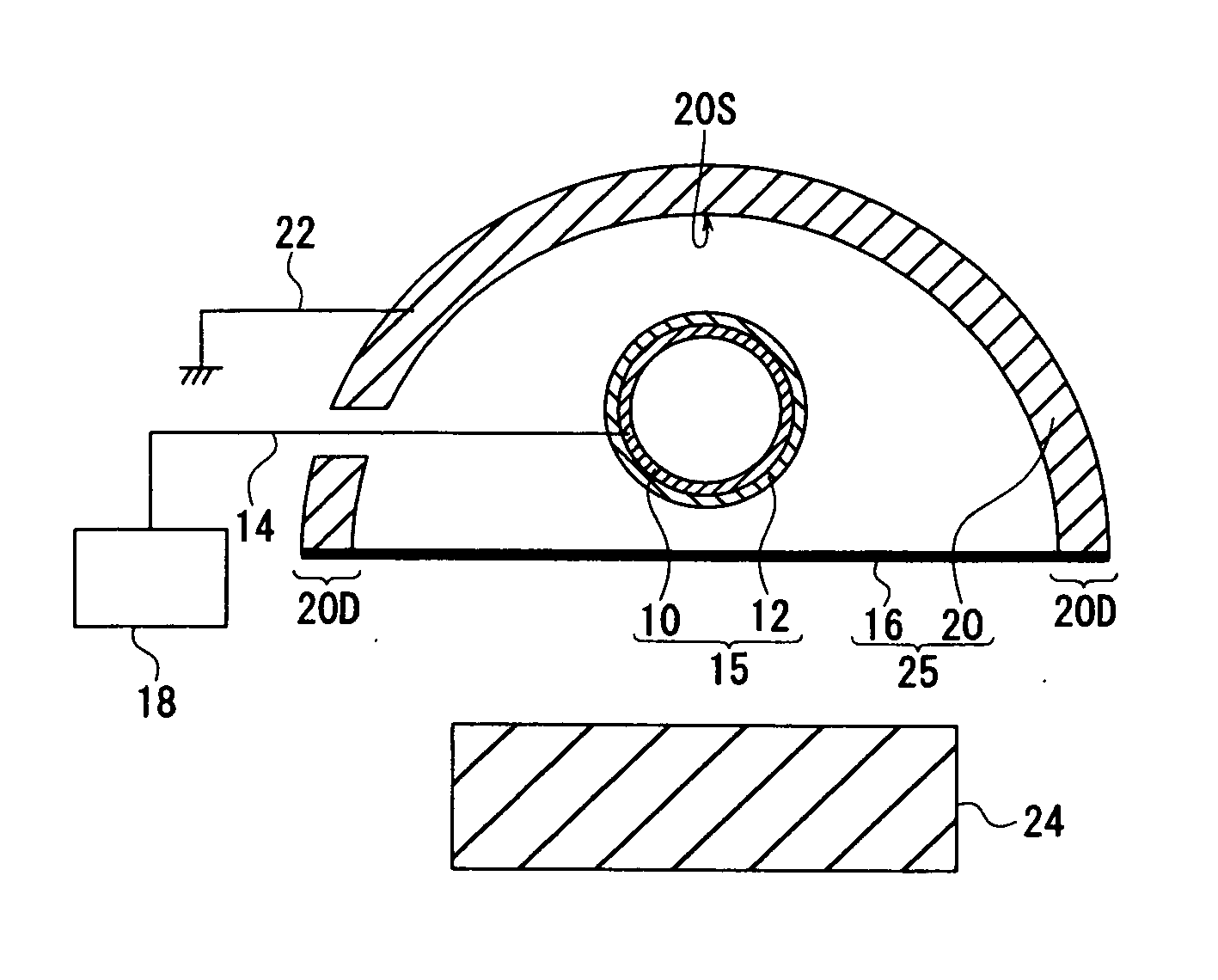
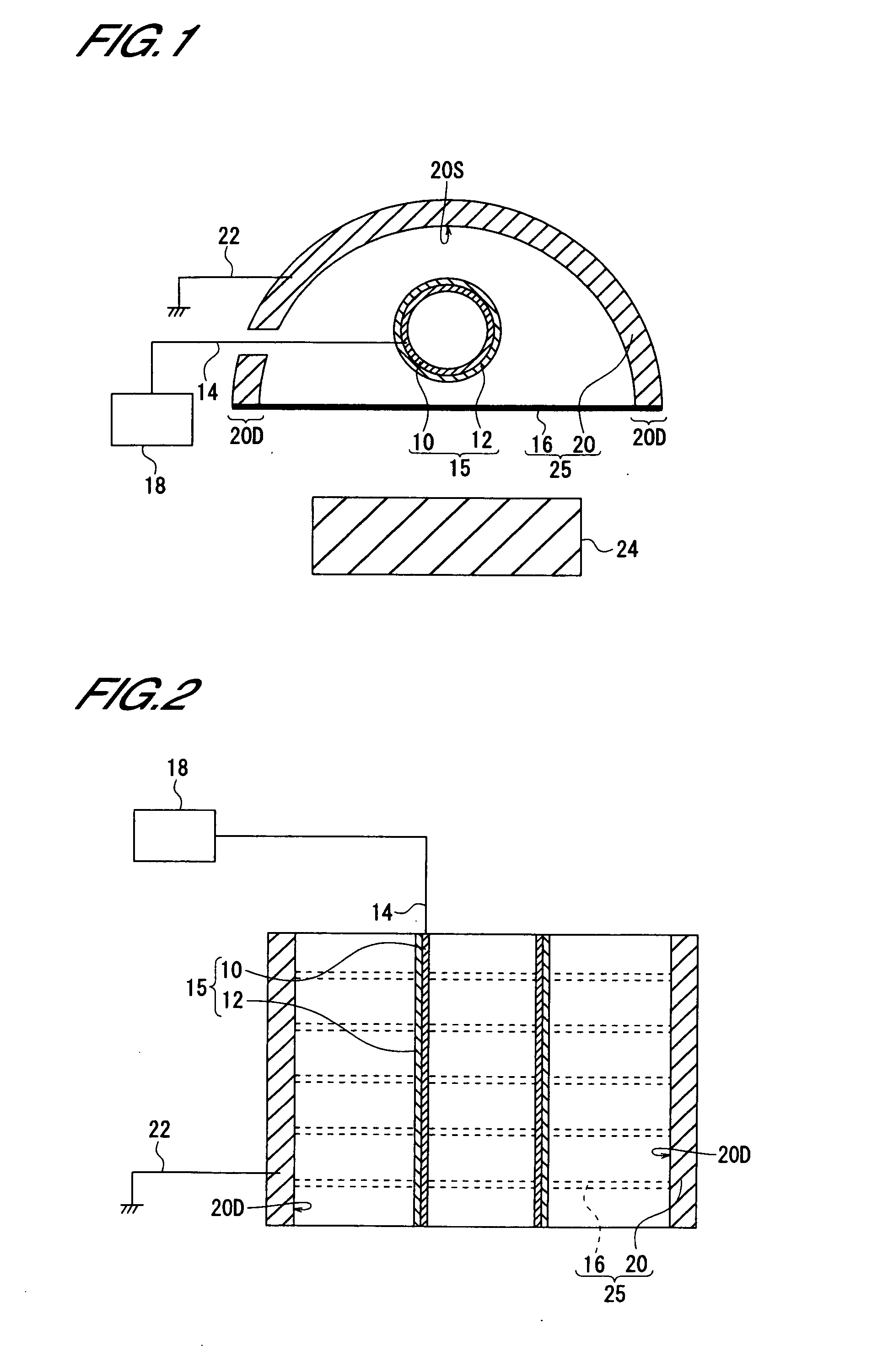
[0096] The structure of the first dielectric barrier discharge excimer light source in accordance with the present invention and the operation principle thereof will be described hereinbelow with reference to FIG. 1 and FIG. 2. FIG. 1 is a schematic transverse sectional view obtained by cutting the first dielectric barrier discharge excimer light source in accordance with the present invention along the direction perpendicular to the longitudinal direction of the anode. FIG. 2 is a schematic vertical sectional view obtained by cutting the dielectric barrier discharge excimer light source in accordance with the present invention along the direction parallel to the longitudinal direction of the anode.

[0097] An anode electrode 10 is composed of a straight elongated cylindrical body and has a structure in which the outer periphery of the cylindrical body is covered with a dielectric body 12. An anode 15 comprises the anode electrode 10 and the dielectric body 12. In the explanation bel...

embodiment 2

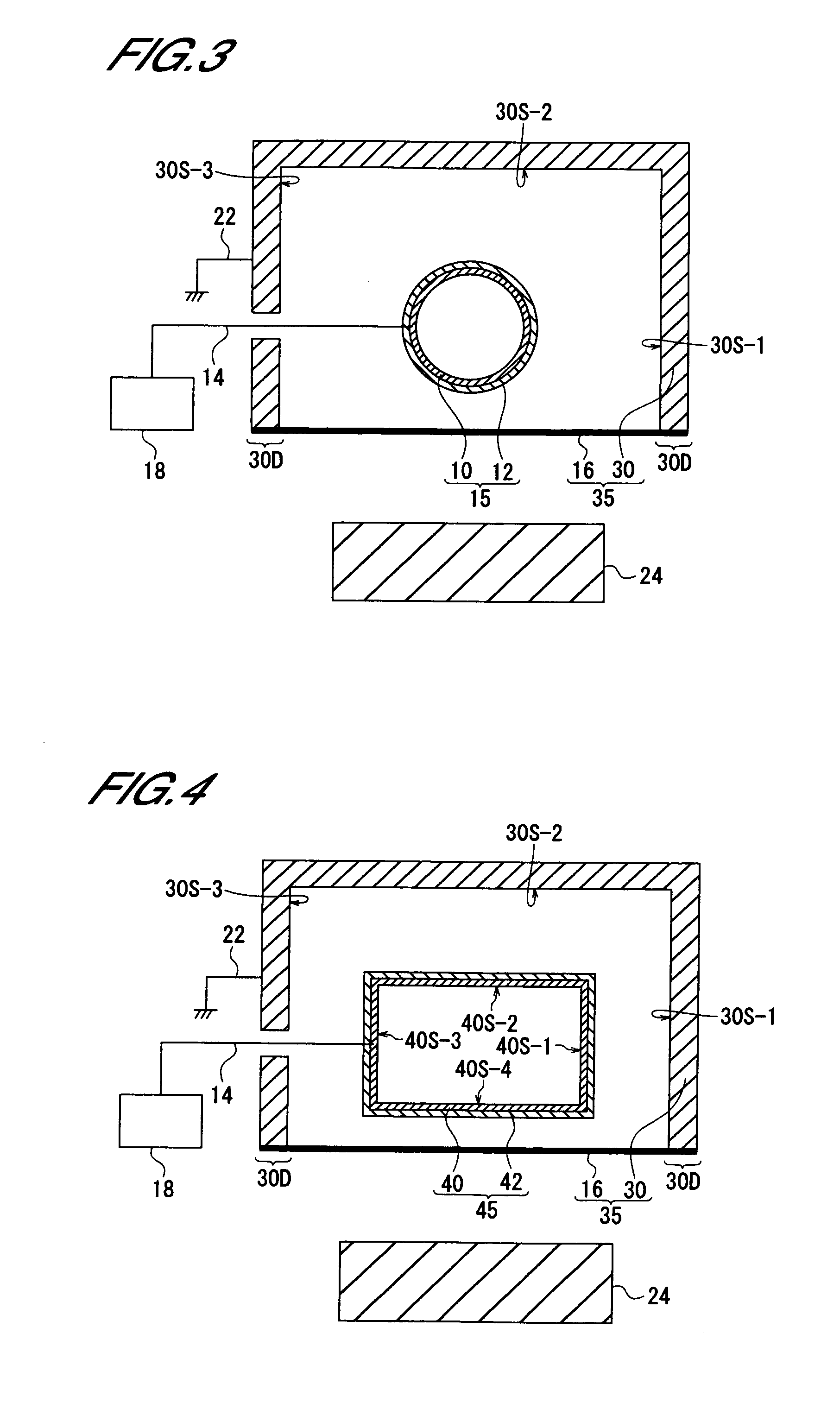
[0111]FIG. 3 illustrates a structure of the second dielectric barrier discharge excimer light source in accordance with the present invention. FIG. 3 is a schematic transverse cross-sectional view of the second dielectric barrier discharge excimer light source in accordance with the present invention, this view being taken within a plane perpendicular to the longitudinal direction of the anode. Further, the schematic vertical cross-sectional view in the plane parallel to the longitudinal direction of the anode is similar to that shown in FIG. 2 and is therefore omitted. Furthermore, as a rule, in the explanation hereinbelow, only the transverse cross-sectional view of the light source is shown, and the vertical cross-sectional view similar to that shown in FIG. 2 is omitted unless considered especially necessary.

[0112] A feature of the second dielectric barrier discharge excimer light source comprising an anode electrode 10 composed of a straight long hollow cylindrical body covere...

embodiment 3

[0114]FIG. 4 illustrates a structure of the third dielectric barrier discharge excimer light source in accordance with the present invention. FIG. 4 is a schematic transverse cross-sectional view of the third dielectric barrier discharge excimer light source in accordance with the present invention, which is perpendicular to the longitudinal direction of the anode. Further, the schematic vertical cross-sectional view in the plane parallel to the longitudinal direction of the anode is similar to that shown in FIG. 2 and is therefore omitted.

[0115] A feature of the third dielectric barrier discharge excimer light source comprising an anode electrode 40 composed of a straight long hollow cylindrical body covered with a dielectric body and a long cathode portion 30 surrounding the anode electrode 40 is the same as in the above-described first dielectric barrier discharge excimer light source. However, the shapes of the anode electrode 40 and the cathode portion 30 are different. The an...


PUM


Abstract

An anode electrode 10 is composed of a straight elongated cylindrical body, and the outer periphery of the cylindrical body is covered with a dielectric body 12. Further, a cathode portion 20 has a straight semicylindrical shape. A cathode 25 surrounds the anode, and the anode and cathode are disposed parallel to each other in the longitudinal direction. Further, the cathode comprises a cathode wire group 16. Both ends of the cathode wire group are fixed to both ends 20D in the longitudinal direction of the semicylindrical body constituting the cathode portion, so that a plurality of wires become parallel to each other. A reflective surface for reflecting irradiation in a vacuum ultraviolet region is formed on the surface 20S of the cathode portion at the side facing the anode.

Description

TECHNICAL FIELD [0001] The present invention relates to a vacuum ultraviolet light source for emitting light with a wavelength in a vacuum ultraviolet (VUV) region with a high efficiency. In particular, the present invention relates to a highly efficient dielectric barrier discharge excimer light source that can be used as a vacuum ultraviolet light source (sometimes referred to hereinbelow as “VUV light source”) suitable for cleaning materials with ultraviolet light or reforming the material surface with ultraviolet light. BACKGROUND ART [0002] Gas discharge light sources which use irradiation of B-X transition of an inert gas in a VUV region are well known as spontaneous emission light sources (spontaneous radiation lamps). Light sources which are representative of the gas discharge light sources of this type are VUV spontaneous emission light source using a dielectric barrier discharge that can obtain an intensive light emission generated by a transition of excimer molecules to a...

Claims


Application Information

Patent Timeline
IPC IPC(8): H01J61/04H01J17/04H01J65/00H01J65/04H01S3/038H01S3/0971H01S3/225
CPCH01J61/06H01J61/35H01J65/046H01S3/225H01S3/0382H01S3/0971H01S3/0381H01J65/00H01S3/038
Inventor LOMAEV, MIKHAIL I.LISENKO, ANDREY A.SKAKUN, VICTOR S.SHITZ, DMITRILI V.TARASENKO, VICTOR F.MATSUMOTO, YOSHIIE
Owner SEN ENG
Why Eureka
Try Eureka