Multi-discharge hydraulic vane pump

Inactive Publication Date: 2013-06-20
TRIUMPH ENGINE CONTROL SYST
View PDF8 Cites 6 Cited by
  • Summary
  • Abstract
  • Description
  • Claims
  • Application Information

AI Technical Summary

Benefits of technology

The present invention is a hydraulic vane pump that includes a pump body with an interior pumping chamber and defines an axially extending inlet port and four radially-extending discharge ports. The pump also includes a cam ring with a continuous peripheral cam surface and a rotor mounted for axial rotation within the pumping chamber. A plurality of circumferentially spaced apart and radially extending vanes are mounted for radial movement within slots formed in the rotor. The pump further includes axially opposed first and second wear disks which are disposed within the interior pumping chamber. The first wear disk has an outer periphery that is positioned radially inward of the cam surface and is mounted for sliding movement with respect to the cam surface. The second wear disk is positioned adjacent to the second end surface of the rotor. The technical effects of the present invention include improved thermal expansion of the rotor and vanes, reduced wear and tear on the pump components, and improved pump efficiency.

Problems solved by technology

The centers of these two circles are typically offset, causing eccentricity.
However, system requirements typically vary with operating conditions, so that a fixed displacement fuel pump that is designed as a function of the most demanding engine operating conditions may function with less than desired efficiency under other operating conditions.
However, these prior art arrangements are typically complex and thus add cost to the pumping system.
However, these implementations are at the expense of pump size / weight and reliability because of an increase in pump radial / axial loading and the incorporation of additional moving parts.

Method used


Image

  • Multi-discharge hydraulic vane pump
  • Multi-discharge hydraulic vane pump
  • Multi-discharge hydraulic vane pump

Examples


Embodiment Construction

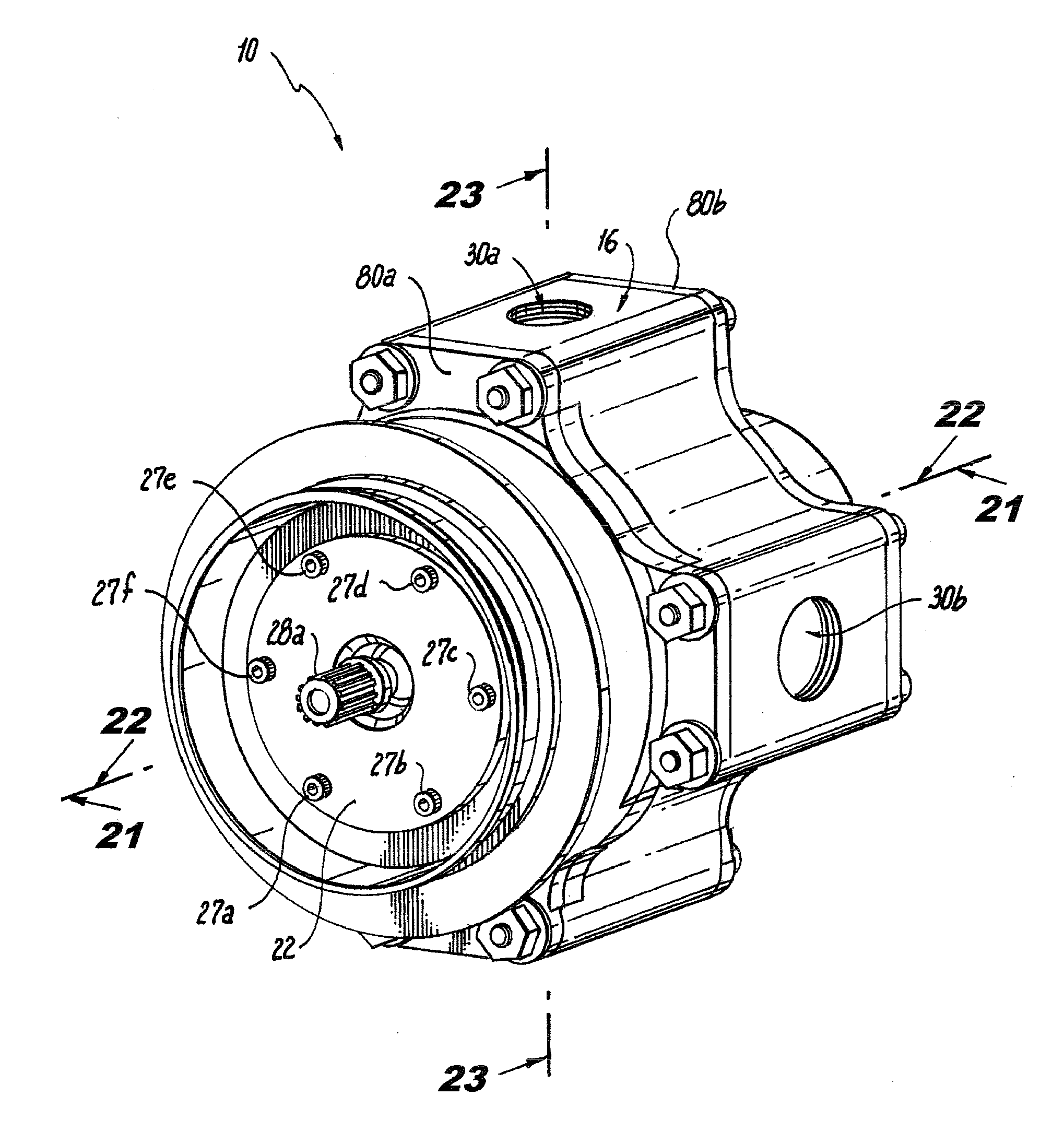
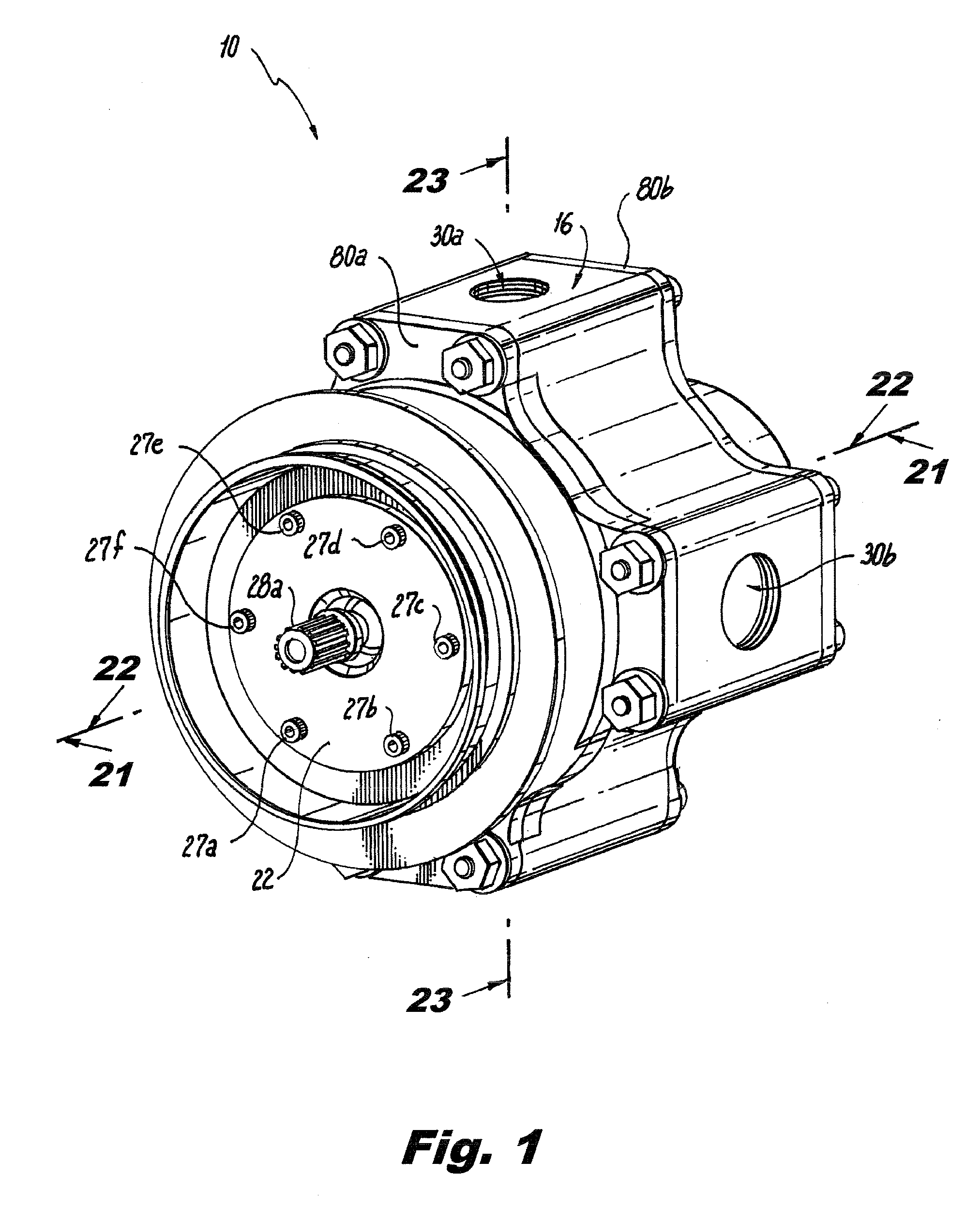
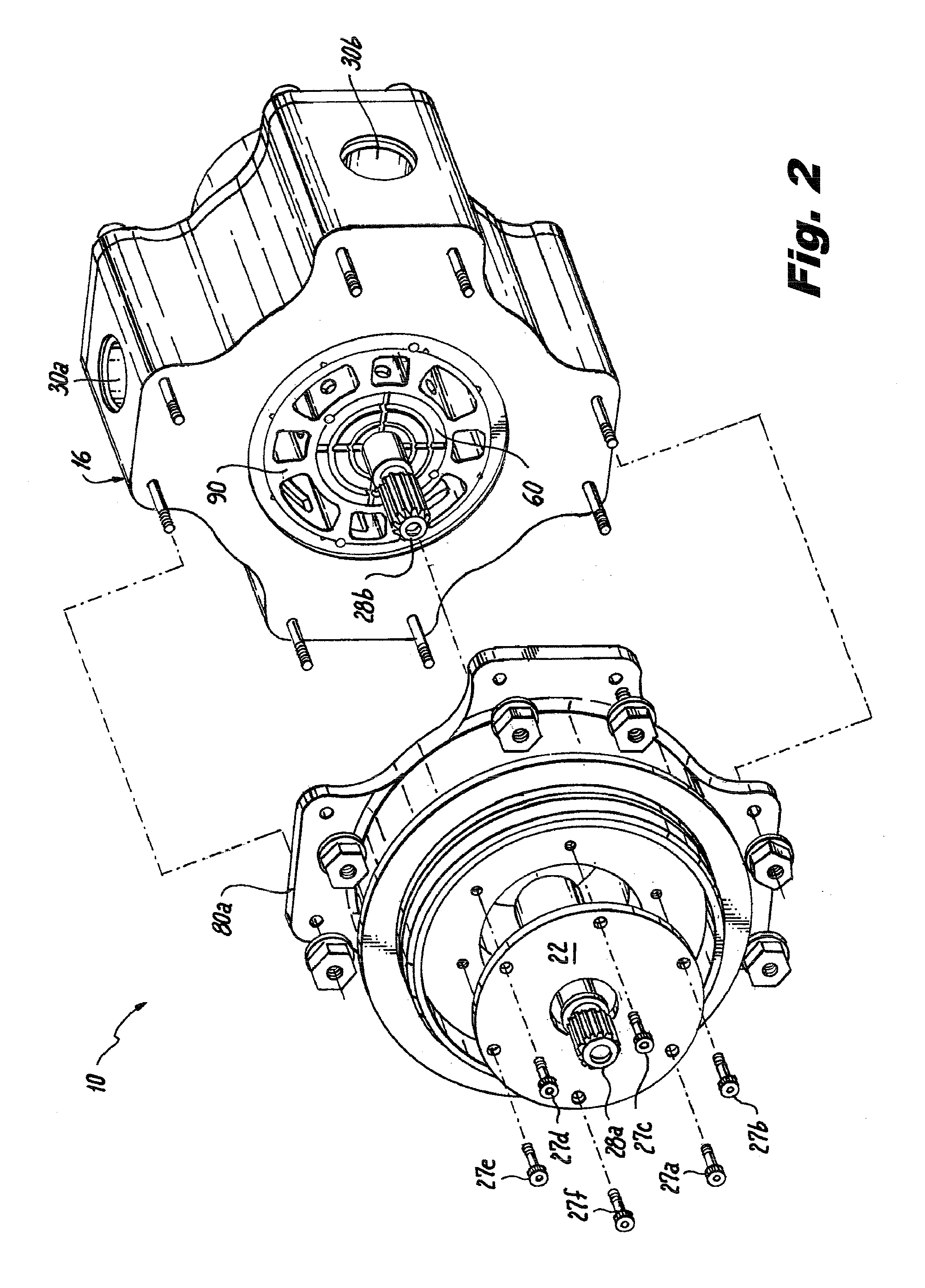
[0057]Disclosed herein are detailed descriptions of specific embodiments of the devices, systems and methods of the present invention. It will be understood that the disclosed embodiments are merely examples of the way in which certain aspects of the invention can be implemented and do not represent an exhaustive list of all of the ways the invention may be embodied. Indeed, it will be understood that the systems, devices, and methods described herein may be embodied in various and alternative forms. The figures are not necessarily to scale and some features may be exaggerated or minimized to show details of particular components. Well-known components, materials or methods are not necessarily described in great detail in order to avoid obscuring the present disclosure. Any specific structural and functional details disclosed herein are not to be interpreted as limiting, but merely as a basis for the claims and as a representative basis for teaching one skilled in the art to various...


PUM


Abstract

A hydraulic vane pump includes a pump body defining an interior pumping chamber, an inlet port, and at least one discharge port. A cam ring is disposed within the interior pumping chamber and defines a continuous peripheral cam surface. A rotor is mounted for axial rotation within the interior pumping chamber. A plurality of vanes are mounted for radial movement within slots formed in the rotor. The pump includes axially opposed first and second wear disks disposed within the interior pumping chamber. The first wear disk is a floating wear disk and has an outer periphery which is positioned radially inward of the cam surface and is adapted and configured to slide axially with respect to the cam surface. The second wear disk is positioned adjacent to a second end surface of the rotor.

Description

GOVERNMENT LICENSE RIGHTS[0001]This invention was made with government support under contract number AATD W911W6-06-D-0005-0004 awarded by the U.S. Army. The government has certain rights in the invention.BACKGROUND OF THE INVENTION[0002]1. Field of the Invention[0003]The subject disclosure is directed to rotary vane pumps, and more particularly, to a balanced split discharge vane pump that provides a combined discharge flow for high fluid demand conditions and a first (primary) discharge flow for low fluid demand conditions, and still more particularly to a multi-discharge vane pump that has an inlet port and four discharge ports, includes a floating side wear disk and a cam ring with internal flow passages, and a rotor assembly with improved under-vane pumping features.[0004]2. Description of Related Art[0005]Rotary hydraulic vane pumps are well known in the art, as disclosed for example in U.S. Pat. No. 4,274,817 to Sakamaki et al. and U.S. Pat. No. 5,064,362 to Hansen. A typical...

Claims


Application Information

Patent Timeline
IPC IPC(8): F04D29/40
CPCF01C21/0863F04C2/3446F04C11/001F04C2240/801F04C15/0096F04C2220/24F04C15/0026
Inventor DONG, XINGENPALUSZEWSKI, PAUL J.DESAI, MIHIR C.
Owner TRIUMPH ENGINE CONTROL SYST
Why Eureka
Try Eureka