Chemical Reactor with Plate Type Heat Exchange Unit

Inactive Publication Date: 2010-12-02
METHANOL CASALE SA
View PDF7 Cites 7 Cited by
  • Summary
  • Abstract
  • Description
  • Claims
  • Application Information

AI Technical Summary

Benefits of technology

[0016]The invention, in particular, is aimed to reduce the head load inside the heat exchange unit of the reactor, and to allow effective operation of the heat exchange unit under high pressure differences between plate interior and exterior and / or in corrosive environment.
[0028]Advantages of the invention are the following: the mechanical strength of the plates is very high, and can be virtually increased as desired. In fact, it is possible to obtain stronger plates by increasing the thickness of the flat walls and / or decreasing the distance (pitch) between the spacer elements. Thus the plates can withstand very high pressure differences between the inside and outside.
[0030]A further advantage is that external surface of the plates, contacting the external fluid, can be perfectly smooth. A smooth external surface can facilitate the discharge of the catalyst and can also be advantageous since it does not have starting points for corrosion.
[0031]Moreover, all advantages deriving from the use of plate type exchangers in isothermal reactors are maintained, such as the high exchange surface, low cost and easy installation.

Problems solved by technology

The chemical reactors with plate type heat exchange, nevertheless, may have some technical limitations and still need of improvement.
Such head loss, especially in large capacity plants, can cause considerable energy consumption of auxiliary items (circulation pumps).
Moreover, the use in a chemical reactor of exchangers with “swelled” type plates, although advantageous for many reasons, involve some technical limitations which have not yet been overcome.
This type of exchanger, in fact, is not adapted to withstand high pressure differences between the plate interior, where the heat exchange fluid circulates, and the outside the plates themselves, subjected to the pressure of the reactor.
Use of swelled plate exchangers is known, for example, in reactors for synthesis of methanol operating at 70-80 bars, but for higher pressure differences (e.g. about 100 bars and beyond) they do not appear to be easily applicable.
The resistance to flattening, in fact, is substantially determined by the thickness of the plates and by the pitch of the welding points between the plates themselves; the thickness, however, cannot be increased beyond certain limits since the swelling process would be impossible, and for the same reason it is not possible to diminish the pitch of the welding points (i.e. bring them closer together) beyond a certain limit.
It must also be pointed out that the manufacturing process, comprising the abovementioned high pressure hydraulic swelling, is relatively costly.
The above-illustrated problems have up to now prevented or limited the diffusion of the plate heat exchangers in chemical reactors operating at very high pressure and / or in aggressive environments.

Method used


Image

  • Chemical Reactor with Plate Type Heat Exchange Unit
  • Chemical Reactor with Plate Type Heat Exchange Unit
  • Chemical Reactor with Plate Type Heat Exchange Unit

Examples


Embodiment Construction

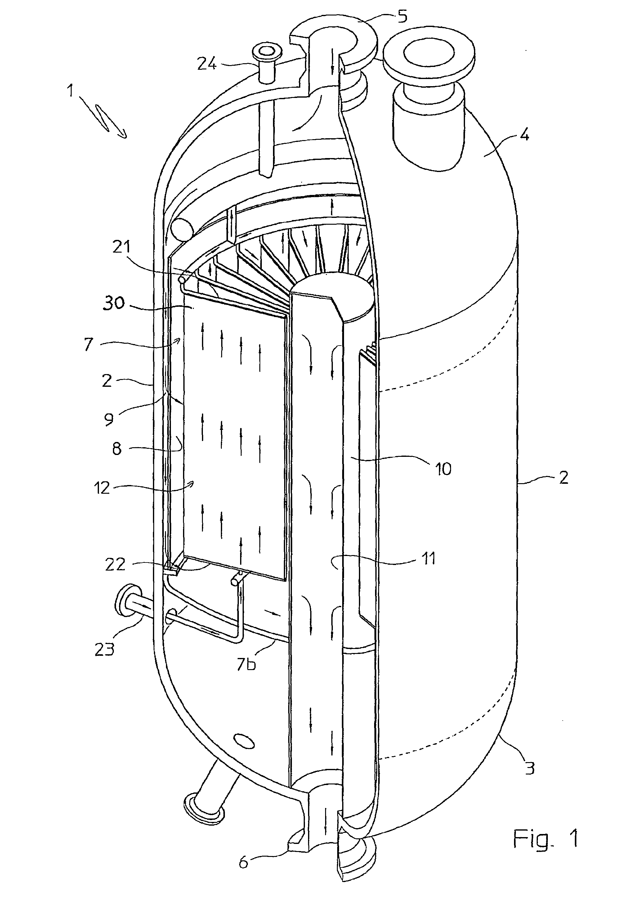
[0039]With reference to FIG. 1, an isothermal chemical reactor 1 is shown which comprises a cylindrical shell 2, with vertical axis, a lower end 3 and an upper end 4, respectively equipped with a flange 5 for the inlet of the reagents and a flange 6 for the outlet of the reaction products.

[0040]The example of FIG. 1 refers to a catalytic reactor, for example for the synthesis of methanol, which comprises a catalytic rack 7, of substantially cylindrical and annular structure. Said catalytic rack 7 is essentially composed of an external cylindrical wall 8, an internal cylindrical wall 10 and an annular bottom 7b. The outer wall 8 defines, with the jacket 2, an interspace 9 of reduced width. The rack 7 is destined to contain a mass of an appropriate catalyst, not shown.

[0041]Said outer wall 8 and said inner wall 10 are perforated in order to allow the passage of the reagent gases from the interspace 9 into the rack 7, and to allow the passage of the gaseous reaction products from the r...


PUM


Abstract

An isothermal chemical reactor (1) is described comprising a plate (30) heat exchange unit (12), immersed in a catalytic bed (7) and destined to heat or cool the reagents in order to maintain the reaction temperature in a predetermined range; said plates (30) are formed by two flat walls (31, 32) and longitudinal spacers (33), with obtainment of parallel channels (34) for the circulation of a heat exchange fluid.

Description

FIELD OF APPLICATION[0001]In its most general aspect, the invention relates to the technical field of chemical reactors internally equipped with a plate heat exchange unit or plate heat exchanger.[0002]The invention is applicable, as a non-limiting example, to isothermal or pseudo-isothermal chemical reactors for exothermic or endothermic heterogeneous reactions, equipped with an internal heat exchanger immersed in a catalytic layer, or to reactors equipped with an internal heat exchanger which in operating conditions is immersed in a fluid.PRIOR ART[0003]Different types of chemical reactors are known equipped with at least one internal heat exchanger, adapted to provide or remove heat from the chemical reaction which is carried out in the reactor itself.[0004]A first example is represented by the so-called isothermal or pseudo-isothermal reactors, generally comprising a heat exchanger, immersed in a catalytic layer, with the task of removing heat from the reagents, in case of exoth...

Claims


Application Information

Patent Timeline
IPC IPC(8): B01J19/00
CPCB01J8/0214B01J8/0285B01J19/0013B01J2208/0015F28F2240/00F28D9/0006F28D9/0062B01J19/24B01J2219/00085
Inventor RIZZI, ENRICOFILIPPI, ERMANNOTAROZZO, MIRCO
Owner METHANOL CASALE SA
Why Eureka
Try Eureka