
Light-emitting device and method of making same

Inactive Publication Date: 2006-06-01
AVAGO TECH INT SALES PTE LTD
View PDF9 Cites 18 Cited by
  • Summary
  • Abstract
  • Description
  • Claims
  • Application Information

AI Technical Summary

Benefits of technology

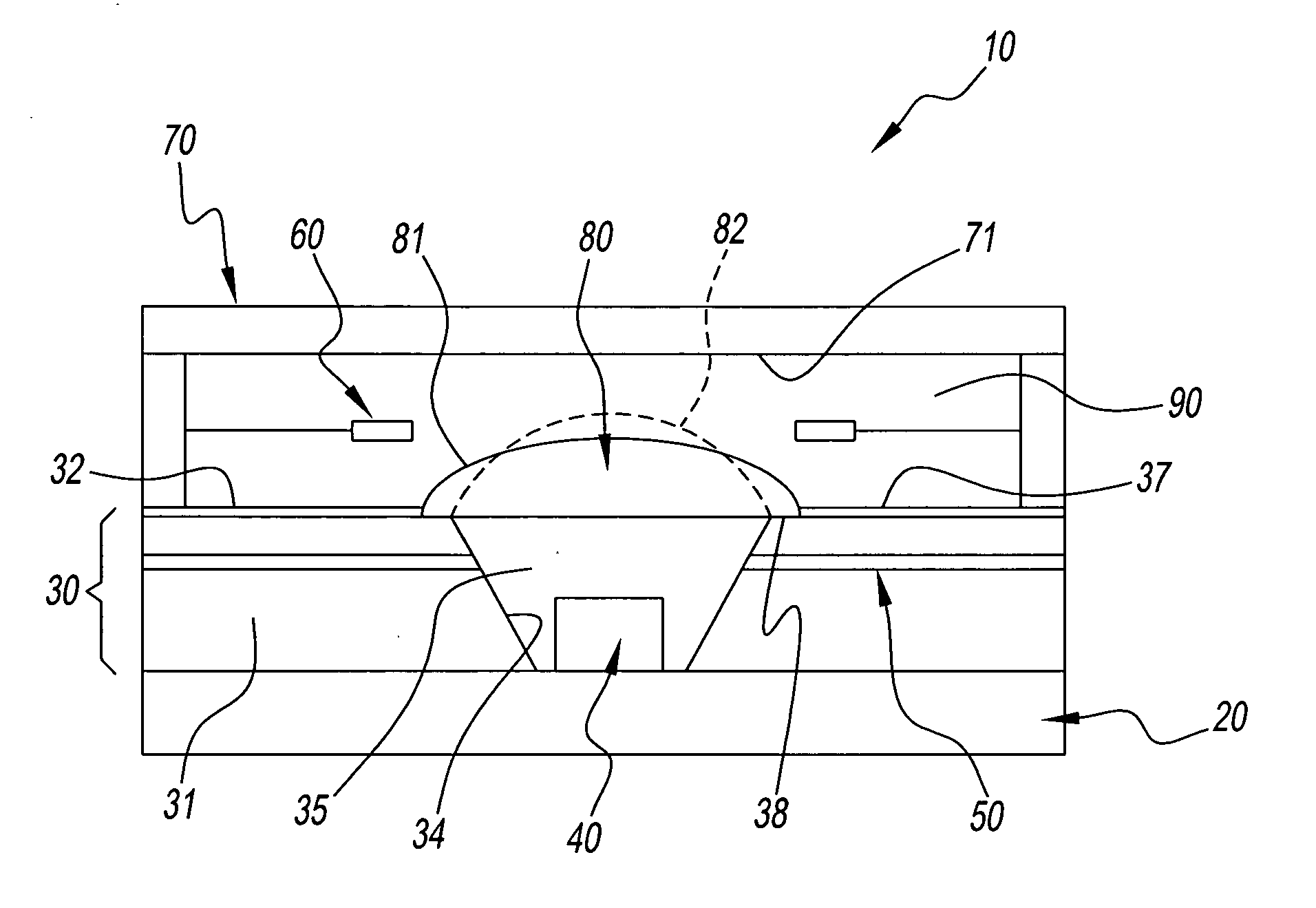
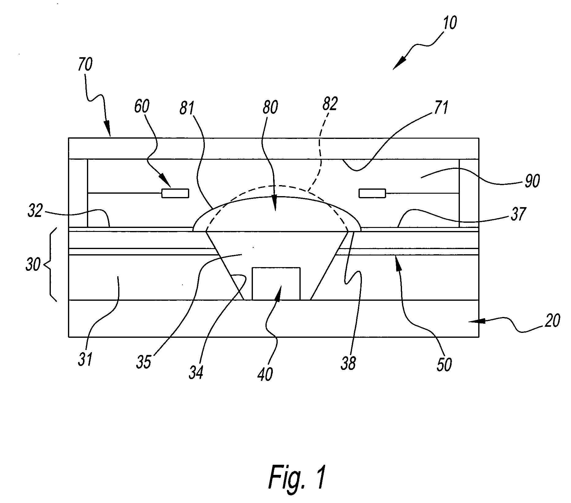
[0017] The light-emitting device of the present invention is a small device wherein the lens system and the light-emitting device are one unit, and is used for various purposes that require changing the condensed state of light. It can be used for purposes that require a device that is easy to handle, has a high operating precision, and a small-scale illumination, such as in medical devices. The light-emitting device allows for separate light emission and control of the lens system thereof. As a result, there is an advantage in that the lens system can be controlled, that is, the focal point distance or the irradiation distance can be changed, whether the lighting by the light-emitting device is on or off.

Problems solved by technology

Nevertheless, there is a problem when the light-emitting device and the device for adjusting the condensed state are separate parts, they are not convenient to handle, and they are difficult to adjust in order to produce with good precision the desired condensed state.

Method used


Image

  • Light-emitting device and method of making same
  • Light-emitting device and method of making same
  • Light-emitting device and method of making same

Examples


second embodiment

[0046] A light-emitting device 110 in FIG. 3, which is the second embodiment, has the same primary structural parts as light-emitting device 10 in FIG. 1. The structural parts shown by numbers wherein 100 is added to the reference number in FIG. 1 have the same effect as the structural part shown in FIG. 1. What should be noted with respect to light-emitting device 110 in FIG. 3 is that the dimensions of the opening of open part 134 are relatively large. As a result, light-emitting device 110 is structurally characterized in that, in addition to almost the entire top surface of bottom container 30, there is a hydrophilic part 137 at the area around the outside of the top surface of resin 135, and electrode 150 comprises a horizontal part 151 extending horizontally and an inclined part 152 extending along the inside surface of open part 134.

[0047] It is also possible to make a transparent lid-like member of a pre-determined thickness that engages with the top end of open part 134 as ...

third embodiment

[0048] A light-emitting device 210 in FIG. 4, which is the third embodiment, is a modified version of light-emitting device 10 in FIG. 1 and differs from light-emitting device 10 and light-emitting device 110 in that it does not have the surface modified part that extends horizontally. The structural parts represented by numbers wherein 200 has been added to the reference number in FIG. 1 have the same effect as the structural parts in FIG. 1.

[0049] Resin 235 introduced to the inside of open part 234 does not fill the entire open part 235 in light-emitting device 210. As a result, first liquid 280 is disposed aligned on top of resin 235 with the inclined surface of open part 234, which is inclined such that it extends deeper toward the middle of open part 235. Moreover, related to this, first electrode 250 comprises a horizontal part 251 and an inclined part 252 that extends away from the inside surface of open part 234 and virtually parallel along the inside surface, and second ele...

fourth embodiment

[0050] A light-emitting device 310 in FIG. 5, which is the fourth embodiment, is yet another version of light-emitting device 10 in FIG. 1. First liquid 380 is separated from the layer of resin 335 by second liquid 390 and forms a convex dome that points downward toward light-emitting element 340. The structural parts shown by numbers wherein 300 is added to the reference number in FIG. 1 have the same effect as the structural parts shown in FIG. 1.

[0051] According to FIG. 5, top container 370 comprises hydrophilic part 377 that has been formed by surface treatment or another treatment of all of the inside of the top wall except a center portion. First liquid 380 is usually disposed as shown by the solid line on the inside of this hydrophilic part. The rest of airtight space 371 is filled by second liquid 390. This differs from the embodiments in FIGS. 1 through 3 mainly in that the positions of first and second liquids 380 and 390 are reversed.

[0052] First electrode 350 for contro...


PUM


Abstract

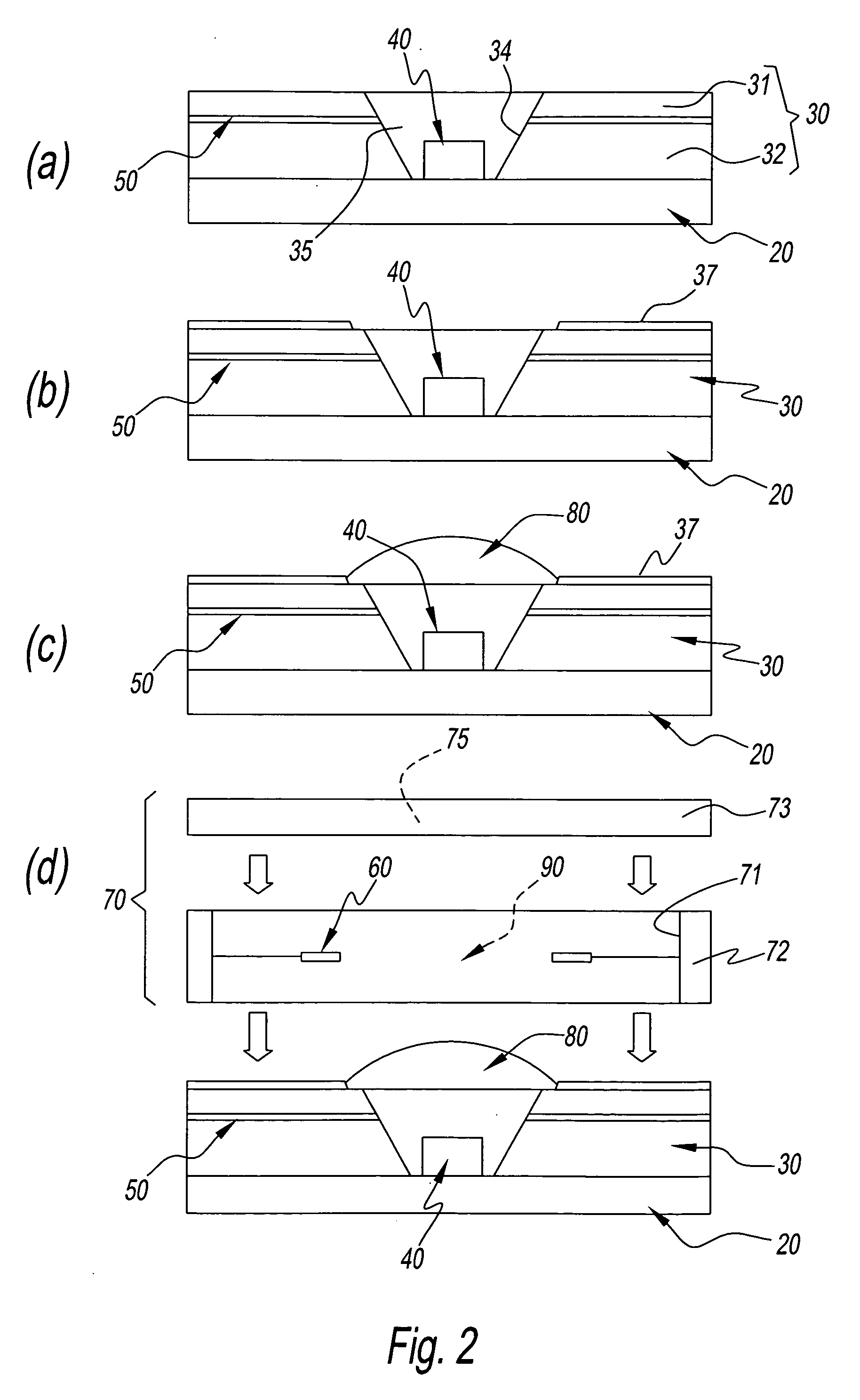
A light-emitting device which comprises as one unit a semiconductor light-emitting element; a first liquid for condensing the light from the semiconductor light-emitting element; a second liquid that is separate from but contacts the first liquid; an airtight space in which at least first liquid and second liquid are disposed; and first and second electrodes to which voltage is applied so as to change the shape of the interface between first liquid and second liquid and adjust the condensed state of the light from semiconductor light-emitting element.

Description

FIELD OF THE INVENTION [0001] The present invention relates to a light-emitting device that uses LED (light-emitting diode) chips, or other light-emitting elements, and a method for producing the same, and in particular, relates to light-emitting components having the function of condensing the light from the light-emitting elements. DISCUSSION OF THE BACKGROUND ART [0002] Light-emitting diodes wherein a chip is disposed near the tip of a pair of metal leads and this chip is enclosed by a resin shell are generally known as light-emitting devices comprising LED chips. The LED chips are usually disposed inside a cup that is made by press molding at the tip of the metal leads. The cup has the effect of directing upward the light from the light-emitting element. The curved surface at the top of the resin shell has a sufficient curvature and acts as a lens for condensing the light that has been directed upward by the cup, or the light that comes directly from the light-emitting elements,...

Claims


Application Information

Patent Timeline
IPC IPC(8): F21V5/00H01L33/56H01L33/58H01L33/60
CPCG02B3/00G02B3/14G02B26/004H01L33/54H01L33/58
Inventor SHIMONISHI, SUMIOTAKEKUMA, AKIRAYAMAOKA, YOSHIFUMI
Owner AVAGO TECH INT SALES PTE LTD
Learn More