Line narrowing module

a narrowing module and narrowing technology, applied in the direction of active medium materials, instruments, photomechanical devices, etc., can solve the problems of grating failure mode, arf grating failure mode appears faster, and limit of max /sub>and equivalents

Active Publication Date: 2006-06-01
CYMER INC
View PDF2 Cites 14 Cited by
  • Summary
  • Abstract
  • Description
  • Claims
  • Application Information

AI Technical Summary

Problems solved by technology

Existing angle of incidence selection mechanisms for such tuning, e.g., the RMAX and equivalents have some limits in this area, e.g., due to mechanical resonances and the bulk of the RMAX required to be moved at very rapid periodic rates, e.g., 24 kHz and above, and the limitations of moving such optical elements with different (though related) rotating mechanisms for both coarse and fine adjustment of the angle of incidence during operation of the line narrowing module.
In addition, the ArF grating failure mode appears faster than the KrF grating failure mode, which applicants suspect is due to the fact that at around 193 nm an ArF photon is able to ionize the imbedded Al layer, thereby actually activating it for oxygen attack.
While applicants are not sure of this fact, it appears that at around the 248 nm KrF photon is not energetic enough to activate the Al and help it corrode in the presence of oxygen.
Grating degradation is still oxygen content related, but in the case of KrF photons appears to be limited to oxygen transport through the MgF2 layer (or reaction with imbedded oxygen).

Method used


Image

  • Line narrowing module
  • Line narrowing module
  • Line narrowing module

Examples


Embodiment Construction

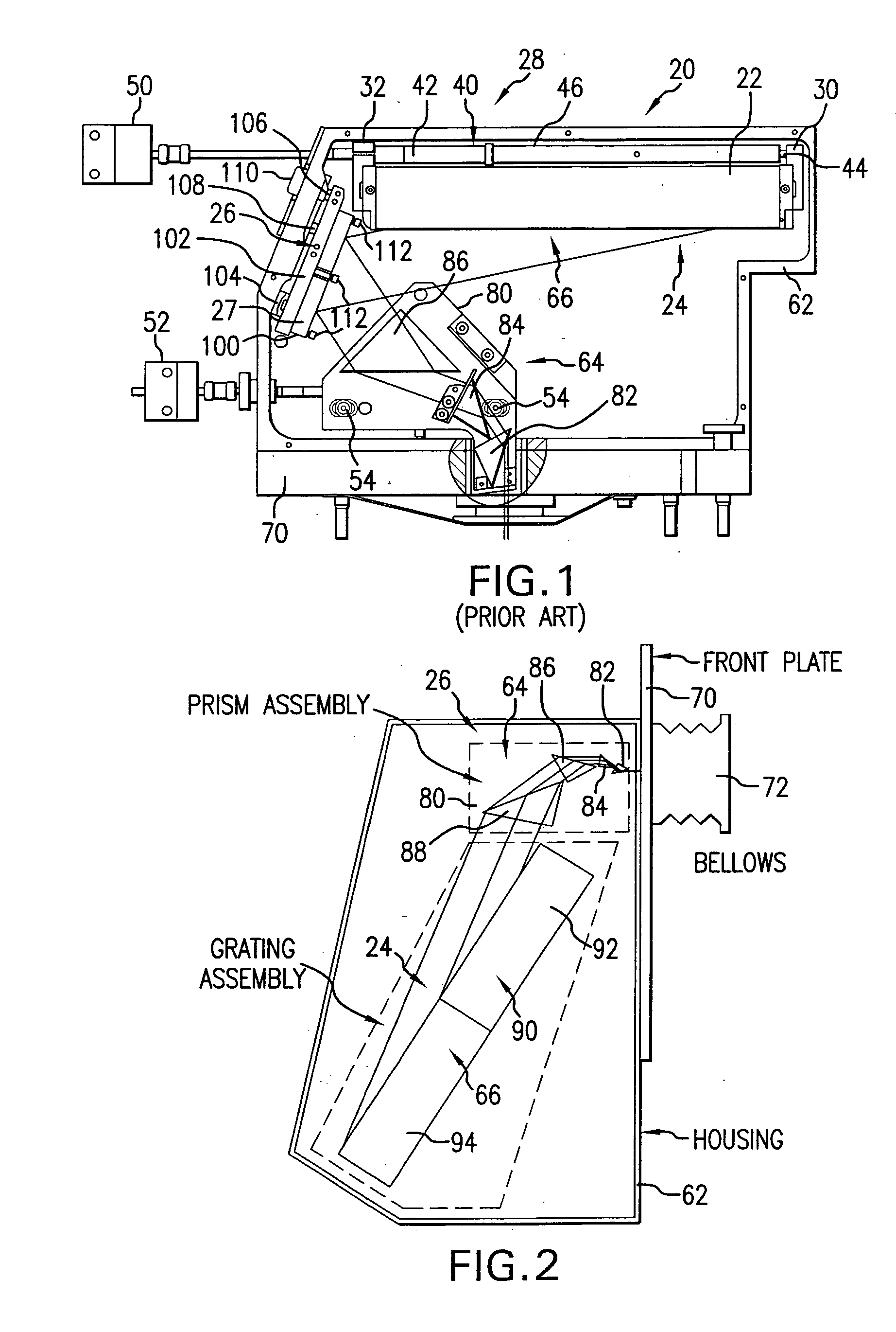
[0034] Turning now to FIG. 1 there is shown a top plan view of a prior art line narrowing module 28. according to aspects of the operation of the prior art line narrowing module of FIG. 1 the positioning of a dispersive center wavelength selection optical element, e.g., a grating 22 and its construction, e.g., its blaze angle, length, groove pitch, and angle of incidence of the laser light pulse beam on the grating (defining, e.g., a nominal optical path to and from the grating 22 within the optical path through the line narrowing module 28—into and out of the line narrowing module 28) etc., define an order of dispersion that will be reflected back along the nominal optical path at what angle and at what wavelength, e.g., 79° at 193.3 nm desired center wavelength. The grating 22 and its construction in and of themselves can be tuned, e.g., using the blaze angle, to maximize the efficiency of the line narrowing module 28, e.g., by selecting an order that contains the largest portion ...


PUM


Abstract

A line narrowing method and module for a narrow band DUV high power high repetition rate gas discharge laser producing output laser light pulse beam pulses in bursts of pulses, the module having a nominal optical path are disclosed which may comprise: a dispersive center wavelength selection optic moveably mounted within an optical path of the line narrowing module, selecting at least one center wavelength for each pulse determined at least in part by the angle of incidence of the laser light pulse beam containing the respective pulse on the dispersive wavelength selection optic; a first tuning mechanism operative in part to select the angle of incidence of the laser light pulse beam containing the respective pulse upon the dispersive center wavelength selection optic, by selecting an angle of transmission of the laser light pulse beam containing the pulse toward the dispersive center wavelength selection optic; a second tuning mechanism operative in part to select the angle of incidence of the laser light pulse beam containing the respective pulse by changing the position of the dispersive center wavelength selection optic relative to the nominal optical path of the line narrowing module; wherein the second tuning mechanism coarsely selects a value for the center wavelength and the first tuning mechanism more finely selects the value for the center wavelength. The apparatus and method may further comprise at least one beam expanding and redirecting prism in the optical path of the line narrowing module; the first tuning mechanism selecting an angle of incidence of the at least a first spatially defined portion of the laser light pulse beam by changing the position of the at least one beam expanding prism relative to the nominal optical path of the line narrowing module. The first and second tuning mechanisms may be controlled by a center wavelength controller during a burst based upon feedback from a center wavelength detector detecting the center wavelength of at least one other pulse in the burst of pulses and the controller providing the feedback based upon an algorithm employing the detected center wavelength for the at least one other pulse in the burst. The first tuning mechanism may comprise an electro-mechanical course positioning mechanism and a fine positioning mechanism comprising an actuatable material that changes position or shape when actuated.

Description

RELATED APPLICATIONS [0001] This application is related to U.S. application Ser. No. ______, filed on the same day as this application, entitled HIGH POWER HIGH PULSE REPETITION RATE GAS DISCHARGE LASER SYSTEM BANDWIDTH MANAGEMENT, Attorney Docket No. 2004-0081-01, assigned to the common assignee of the present application, the disclosure of which is hereby incorporated by reference. The present application is also related to U.S. Pat. No. 5,095,492 issued to Sandstrom on Mar. 10, 1992, entitled SPECTRAL NARROWING TECHNIQUE, and U.S. Pat. No. 5,852,627, issued to Ershov on Dec. 22, 1998, entitled, LASER WITH LINE NARROWING OUTPUT COUPLER, and U.S. Pat. No. 5,898,72, issued to Fomenkov, et al. on Apr. 27, 1999, entitled, Excimer laser with greater spectral bandwidth and beam stability. and U.S. Pat. No. 5,978,409, issued to Das, et al. on Nov. 2, 1999, entitled LINE NARROWING APPARATUS WITH HIGH TRANSPARENCY PRISM BEAM EXPANDER, and U.S. Pat. No. 6,028,879, issued to Ershov on Feb. 2...

Claims


Application Information

Patent Timeline
Patent Type & Authority Applications(United States)
IPC IPC(8): H01S3/22
CPCG03F7/70025G03F7/70041H01S3/005H01S3/036H01S3/08H01S3/08059H01S3/097H01S3/1055H01S3/106H01S3/2251H01S3/08004H01S3/22
Inventor ALGOTS, J. MARTINBERGSTEDT, ROBERT A.GILLESPIE, WALTER D.KULGEYKO, VLADIMIR A.PARTLO, WILLIAM N.RYLOV, GERMAN E.SANDSTROM, RICHARD L.STRATE, BRIANDYER, TIMOTHY S.
Owner CYMER INC
Why Eureka
Try Eureka