Method and system for high speed video encoding using parallel encoders

a video encoder and encoder technology, applied in signal generators, color televisions with bandwidth reduction, signal generators with optical-mechanical scanning, etc., can solve the problems of video encoders that cannot meet the compression speed targets required for cable and satellite head ends or for digital video disk authoring/mastering systems, and may slow down the compression of video sequences

Inactive Publication Date: 2006-06-01
AVAGO TECH WIRELESS IP SINGAPORE PTE
View PDF4 Cites 72 Cited by
  • Summary
  • Abstract
  • Description
  • Claims
  • Application Information

AI Technical Summary

Benefits of technology

[0012] Certain embodiments of the invention may be found in a method and system for high speed video processing using parallel encoders. Aspects of the method may comprise transferring a plurality of encoding groups into a plurality of parallel encoders. The parallel encoders may process intra-coded pictures in the encoding groups and may transfer the processed intra-coded pictures to a plurality of previous parallel encoders. The previous parallel encoders may generate a plurality of parallel outputs based on the transferred processed intra-coded pictures and the transferred encoding groups. The generated parallel outputs may be assembled into an encoded video output.

Problems solved by technology

However, in application spaces where the frame rate and / or the content in each frame is very large, the computational processing capacity of a video encoder, including processing capacity to perform encoding and reconstruction operations, may be limited.
For example, a video encoder may not meet the demands in compression speed targets required for cable and satellite head ends or for Digital Video Disks (DVD) authoring / mastering systems.
This may be of particular concern for the new Advanced Video Coding (AVC) or H.264 standard, where higher processing complexity may arise from the extension of prediction dependencies to a larger number of pictures, resulting in a possible slow down in the compression of the video sequence.

Method used


Image

  • Method and system for high speed video encoding using parallel encoders
  • Method and system for high speed video encoding using parallel encoders
  • Method and system for high speed video encoding using parallel encoders

Examples


Embodiment Construction

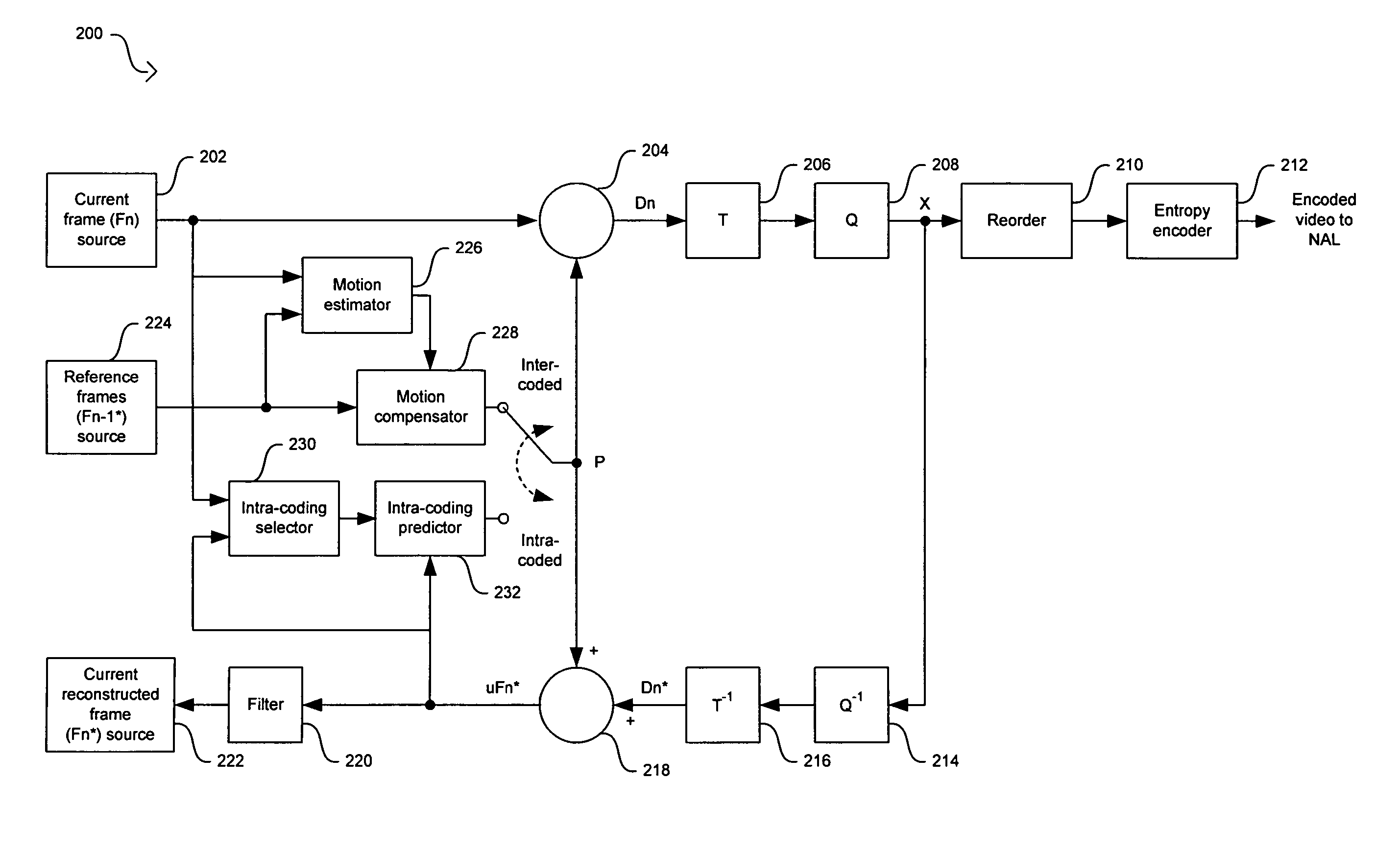
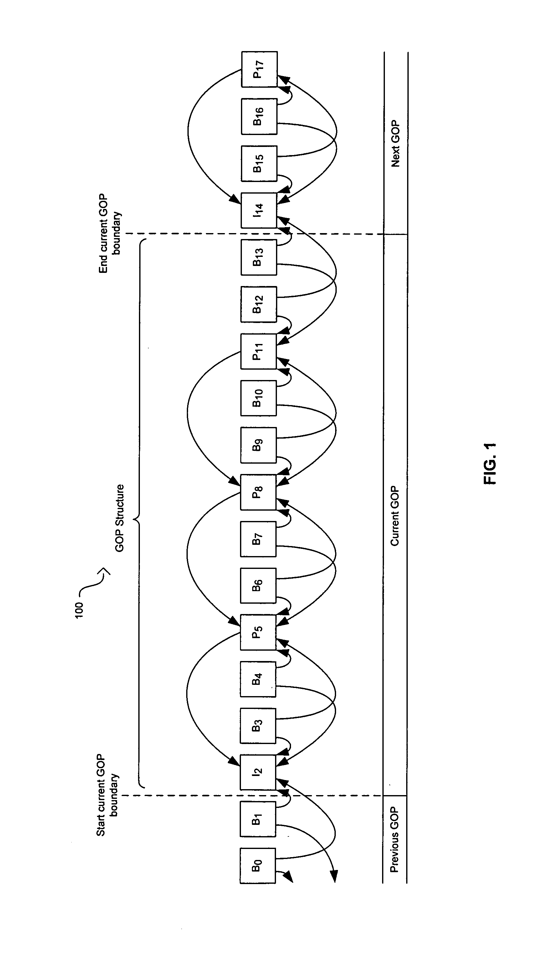
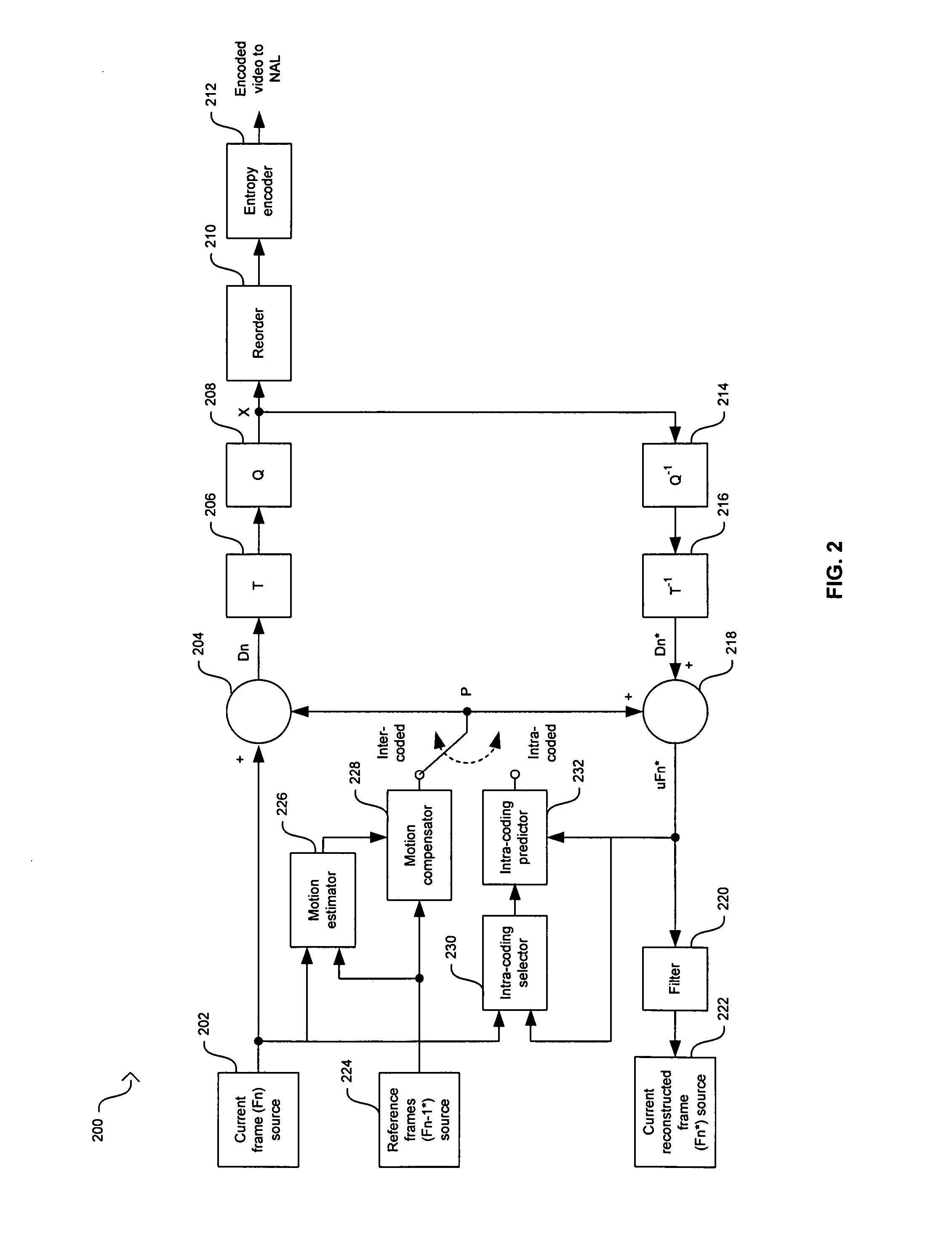
[0031] Certain embodiments of the invention may be found in a method and system for high speed video encoding using parallel encoders. A high speed encoding architecture may comprise a delimiter, a plurality of parallel encoders, an assembler, and a controller. The delimiter may break up a video sequence into encoding groups that are transferred to parallel encoders. The parallel encoders may process and transfer “I’ pictures in the encoding groups to previous parallel encoders or may process and transfer last “P” pictures in the encoding groups to next parallel encoders. The parallel encoders may then encode the transferred pictures and encoding groups to generate parallel outputs. The assembler may assemble an encoded video output from the parallel outputs based on timing information. The controller may be utilized to control the operation of the delimiter, the parallel encoders, and the assembler. This architectural approach may provide the compression speed targets necessary for...


PUM


Abstract

In a video processing system, a method and system for high speed video encoding using parallel encoders are provided. A delimiter may break up a video sequence into encoding groups that are transferred to a plurality of parallel encoders. The parallel encoders may process and transfer intra-coded pictures in the encoding groups to previous parallel encoders or may process and transfer last predictive pictures to next parallel encoders. When intra-coded pictures are transferred, the encoding group may correspond to that of a GOP structure. When predictive pictures are transferred, the encoding group may end in at least one bidirectional-predictive picture. The parallel encoders process the transferred intra-coded pictures or transferred predictive pictures to generate a plurality of parallel outputs. An assembler assembles an encoded video output from the parallel outputs based on timing information. A controller controls the operation of the delimiter, the parallel encoders, and the assembler.

Description

CROSS-REFERENCE TO RELATED APPLICATIONS / INCORPORATION BY REFERENCE [0001] Not applicable. FIELD OF THE INVENTION [0002] Certain embodiments of the invention relate to the compression of video signals. More specifically, certain embodiments of the invention relate to a method and system for high speed video encoding using parallel encoders. BACKGROUND OF THE INVENTION [0003] In video compression systems, a source video sequence may be partitioned into successive groups of pictures or GOPs, where each GOP picture may be of a pre-defined picture coding type. These picture coding types may comprise intra-coded pictures, predicted pictures, and bidirectional-predicted pictures. The intra-coded or “I” pictures may only use the information within the picture to perform video compression. These self-contained “I” pictures provide a base value or anchor frame that is an estimate of the value of succeeding pictures. Each GOP may generally start with a self-contained “I” picture as the referen...

Claims


Application Information

Patent Timeline
Patent Type & Authority Applications(United States)
IPC IPC(8): H04N7/12H04N11/04H04B1/66H04N11/02
CPCH04N19/61H04N19/593H04N19/577H04N19/573H04N19/436
Inventor ROBEY, JOSHUAKNIGHT, ROY F.GREARSON, PAUL DOUGLAS
Owner AVAGO TECH WIRELESS IP SINGAPORE PTE
Why Eureka
Try Eureka