CFC radiant heater

a radiant heater and heater technology, applied in the field of ir radiant heaters, can solve the problems of lack of two-dimensional character of radiating surface arrangement, carbon filaments disclosed in these documents cannot be assembled into arbitrary two-dimensional heating elements, carbon bands cannot be arranged in arbitrary two-dimensional patterns, etc., to achieve a large degree of flexibility in possible configurations, high output, and long service li

Inactive Publication Date: 2006-06-01
HERAEUS NOBLELIGHT GMBH
View PDF4 Cites 5 Cited by
  • Summary
  • Abstract
  • Description
  • Claims
  • Application Information

AI Technical Summary

Benefits of technology

[0013] The goal of the invention is to develop an IR radiator, which can be operated at typical power-grid voltages, at the same time has high o

Problems solved by technology

However, the carbon filaments disclosed in these documents cannot be assembled into arbitrary two-dimensional heating elements, because the material can have only an elongated and constant width arrangement.
However, such carbon bands cannot be arranged in arbitrary two-dimensional patterns, because the bands only permit minimal deviations from a parallel arrangement.
However, such arrangements lack the two-dimensional character of a radiating surface.
Such heating elements made of SiC or graphite are brittle and rigid, so that they are very sensitive to fracture.
The heating element is also electrically contacted rigidly by screws, so that heat expansion introduces there a

Method used


Image

  • CFC radiant heater
  • CFC radiant heater
  • CFC radiant heater

Examples


production example

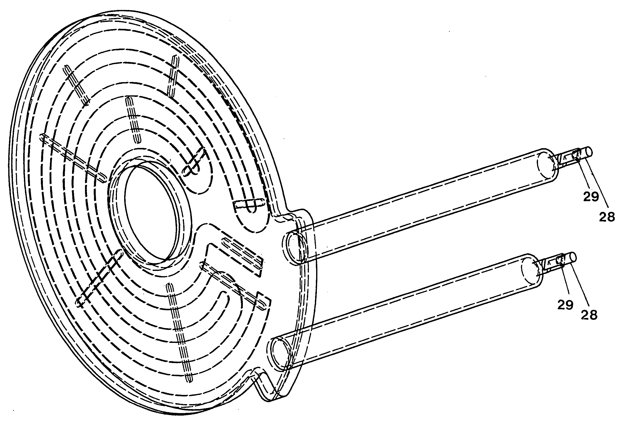
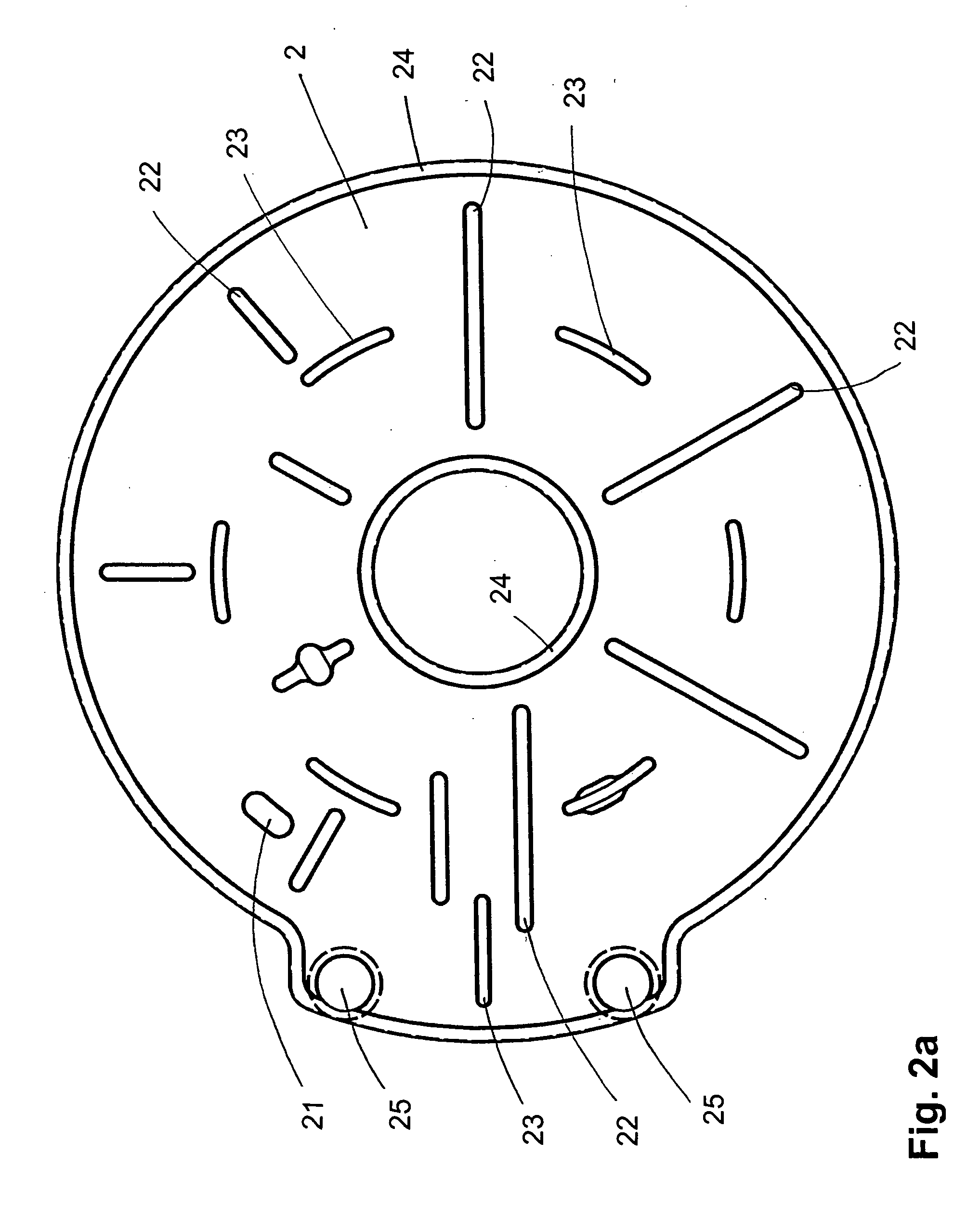
[0044] An opaque quartz glass plate 2 of sufficient thickness is cut into the necessary shape for the bottom side 2, then the recesses are milled and ground. In this way, the edge 24 and the spacers 23 remain at their original height and the contact pieces 22 for the filament stand at a lower height. Finally, the openings, in which the tubes for the electric contacting and the current leadthrough are placed, are bored. Edges are smoothed or fire-polished, if necessary.

[0045] Then tubes made of quartz glass are set on the bore holes, in each of which tubes a current leadthrough is arranged. Additionally, nozzles 27 for establishing a vacuum and for introducing flushing gas are located at these tubes.

[0046] The cover plate 3 for the top side is cut and ground from pure quartz glass. In particular, openings 31 for later welding of the plate to the spacers 23 of the opaque plate 2 are formed.

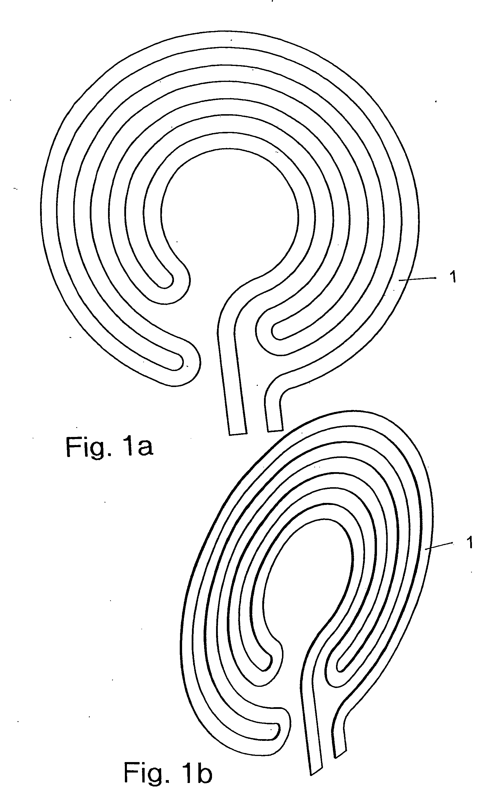
[0047] The heating element 1 is cut from a CFC sheet material by a water jet and then coated ...


PUM


Abstract

An IR radiant heater has at least one planar carbon heating element (1) arranged in a housing, which is transparent or at least partially transparent to IR radiation. At least one carbon heating element (1) is a CFC web arranged in a plane and arranged between two plates (2, 3), of which at least one is transparent or partially transparent.

Description

BACKGROUND OF THE INVENTION [0001] The present invention relates to an IR radiant heater having at least one two-dimensional (planar) carbon filament in a housing that is transparent or at least partially transparent to IR radiation. [0002] Such an IR radiator is realized according to European published patent application No. EP 0 881 858 A2 with a single filament arranged in a round tube and in German published patent applications Nos. DE 44 38 871 A1 and DE 44 19 285 A1 with several carbon filaments arranged next to each other. The carbon materials used there consist of parallel carbon fibers, which are connected by resin. These structures are carbonized and graphitized before installation in the radiator. [0003] The radiator disclosed in EP 0 881 858 is not suitable for uniform two-dimensional radiation. DE 44 38 871 and DE 44 19 285 relate to the use of comparable filaments, but with the goal of achieving two-dimensional (2D) radiation. [0004] However, the carbon filaments discl...

Claims


Application Information

Patent Timeline
IPC IPC(8): F24C7/00
CPCH05B3/145H05B2203/032H05B3/14
Inventor LINOW, SVENFUCHS, STEFANGROB, SIEGFRIED
Owner HERAEUS NOBLELIGHT GMBH
Why Eureka
Try Eureka