Ultrasonic diagnostic apparatus and control method thereof

Inactive Publication Date: 2006-06-01
KK TOSHIBA +1
View PDF6 Cites 96 Cited by
  • Summary
  • Abstract
  • Description
  • Claims
  • Application Information

AI Technical Summary

Benefits of technology

[0012] The present invention has been made in view of the above conditions, and it is an object of the present invention to provide an ultrasonic diagnostic apparatus that can objectively and simply choose a substantially same cr

Problems solved by technology

On the other hand, with respect to the cross-sectional alignment of the latter, in addition to complicated examination by the use of contrast agent, examination must be completed within the limited time due to restriction of the dose of contrast agent.
However, decision of the cross-section under stress based on artificial image memory lacks objectivity and imposes large artificial load.
In addition, in deciding the cross-section afte

Method used


Image

  • Ultrasonic diagnostic apparatus and control method thereof
  • Ultrasonic diagnostic apparatus and control method thereof
  • Ultrasonic diagnostic apparatus and control method thereof

Examples


first embodiment

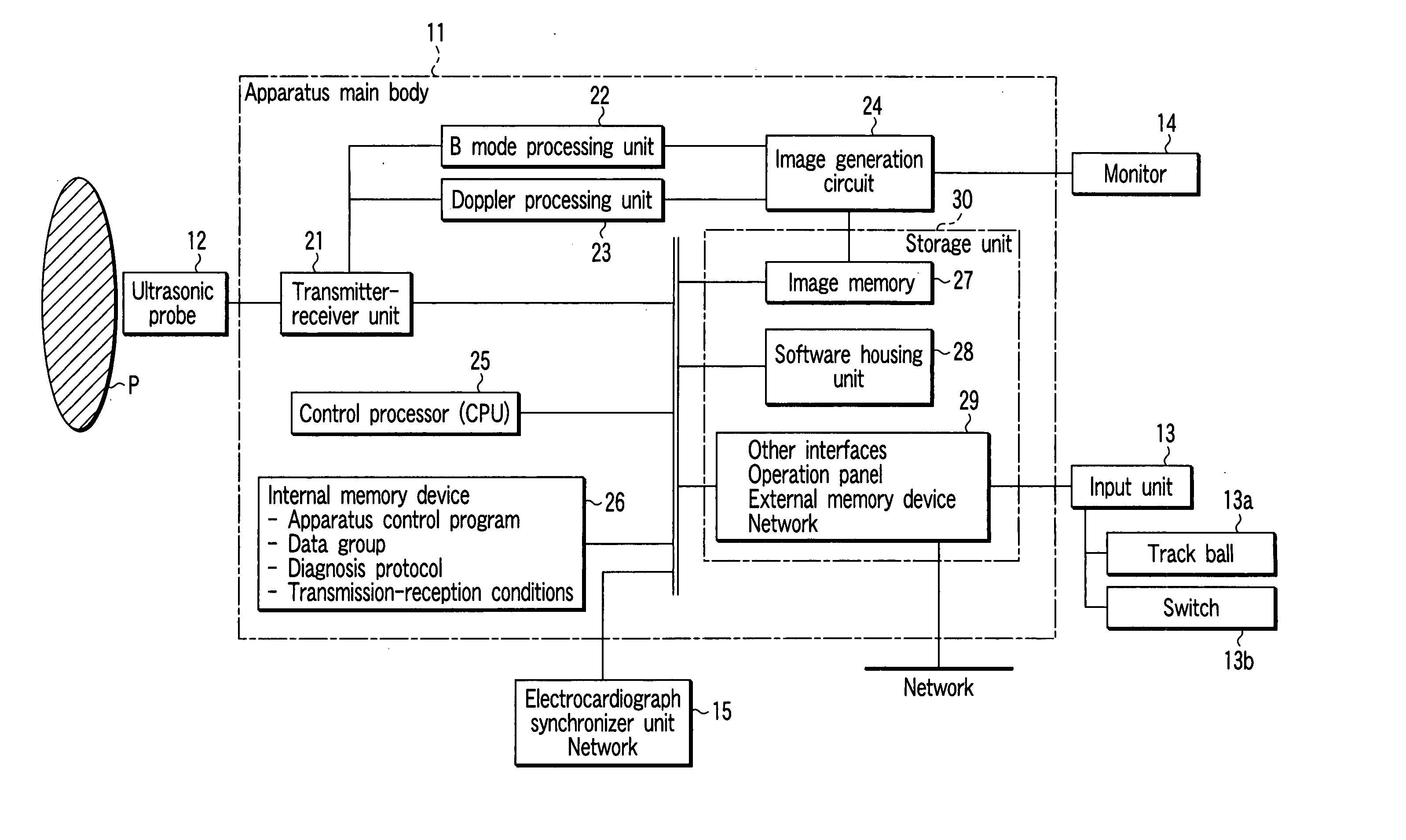
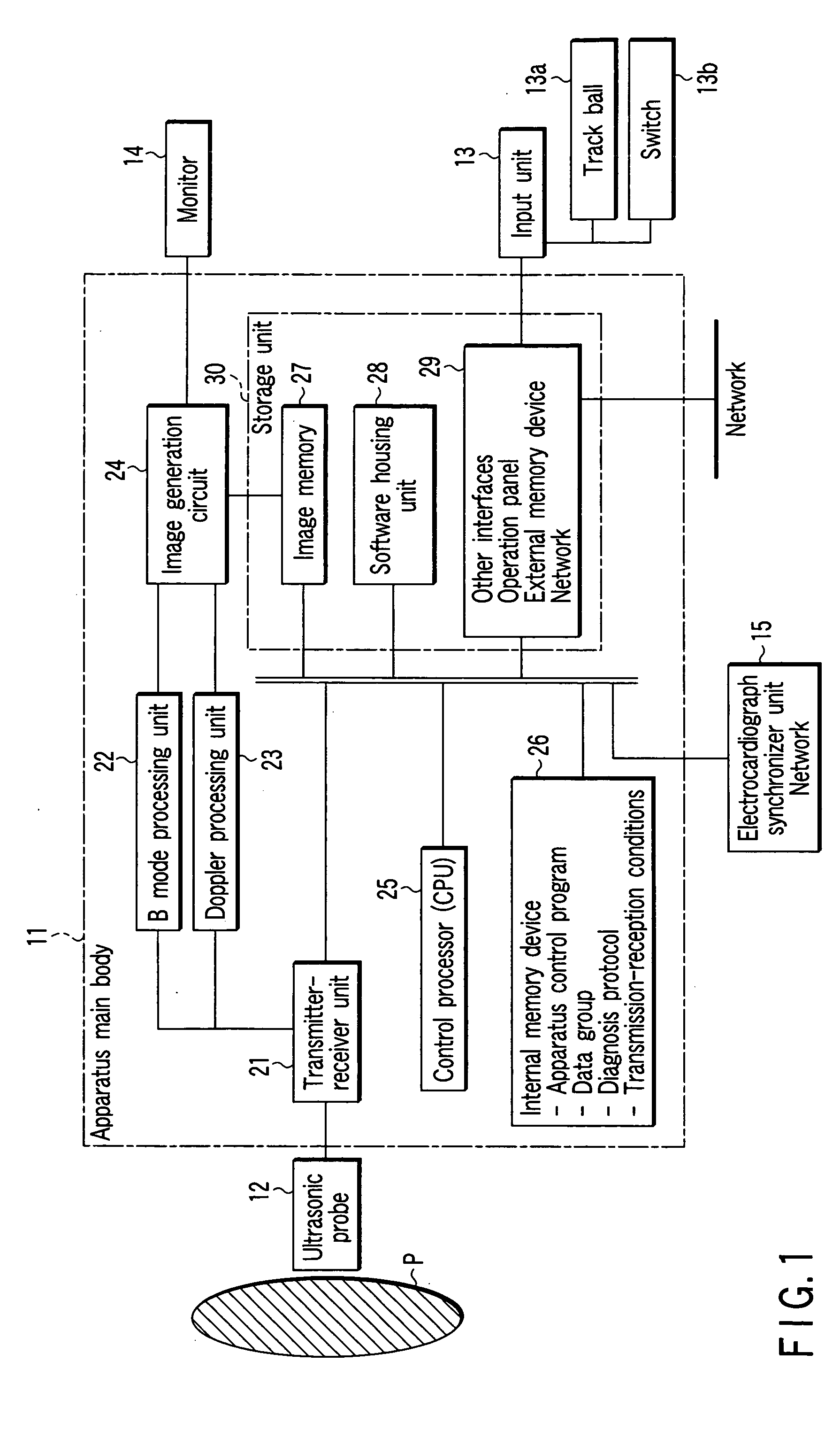
[0032]FIG. 1 is a block diagram of an ultrasonic diagnostic apparatus 1 according to the present embodiment. As shown in the drawing, the ultrasonic diagnostic apparatus 1 comprises an ultrasonic probe 12, apparatus main body 11, external input unit 13 that is connected to the apparatus main body 11 and imports various directions, orders, and information from the operator into the apparatus main body 11, and a monitor 14 which is an external display unit to display images created by the apparatus main body 11. To the input unit 13, a track ball 13a, switch 13b, etc. are installed to set a region of interest (ROI).

[0033] The ultrasonic probe 12 has a piezoelectric vibrator as an acoustic / electric reversible conversion element such as piezoelectric ceramic. Multiple piezoelectric vibrators are arranged in a line and mounted to the head end of the probe 12.

[0034] The apparatus main body 11 is connected to other units, internal memory device 26, and storage unit 30 by the bus as with ...

second embodiment

[0103] Next description will be made on the second embodiment of the present invention. The present embodiment utilizes minor programs (hereinafter, referred to as the “activities”), which are individual component elements of the examination procedure in the system that programs a series inspection procedures in advance and supports the physician's or engineer's examination procedure (workflow). This workflow system is described in detail by, for example, Jpn. Pat. Appln. KOKAI Publication No. 2001-137237.

[0104] In the present workflow system, by “image saving activity,”“image reference display activity,” and “image comparison display activity” as the activities, existing image related storage function, image reference function, and image comparison function are realized.

[0105] In this event, the “image saving activity” means a minor program for saving dynamic images or still images or both of varying imaging modes in the internal memory device 26 or external memory device 29. For...

third embodiment

[0111] Next, the third embodiment according to the present invention will be described. The present embodiment further improves the degree of freedom of diagnostic image selection in image comparison by carrying out ultrasound scan (volume scan) concerning the three-dimensional region in the contrast echo technique implemented in stress examination concerning ischemic heart diseases.

[0112] First of all, a configuration of an ultrasonic diagnostic apparatus 1 according to the present embodiment will be described. In FIG. 1, for the ultrasonic probe 12, a two-dimensional ultrasonic probe with piezoelectric vibrators arranged in a two-dimensional matrix is used. The transmitter-receiver unit 21 supplies the drive signal for volume scan to each of piezoelectric vibrators of the ultrasonic probe 12 in accordance with control signals from the control processor 25.

[0113] Each of the transmitter-receiver unit 21, B-mode processor unit 22, and Doppler processing unit 23 execute the above-m...


PUM


Abstract

In the event that images are acquired for multiple cross-sections (multiple phases) by a predetermined imaging mode in an examination under stress to a subject, images of the same phase acquired by the same imaging mode in an examination before stress to the subject is read and simultaneously displayed as reference images together with current images. The operator can bring the cross-sectional position in the examination under stress in correspondence to the position of the examination before stress by comparing the displayed reference images with the current image.

Description

CROSS-REFERENCE TO RELATED APPLICATIONS [0001] This application is based upon and claims the benefit of priority from prior Japanese Patent Application No. 2004-342400, filed Nov. 26, 2004, the entire contents of which are incorporated herein by reference. BACKGROUND OF THE INVENTION [0002] 1. Field of the Invention [0003] The present invention relates to an ultrasonic diagnostic apparatus, which has an image display function to support ultrasonic image diagnosis and its control method primarily for a complicated examination combining contrast-enhanced ultrasonography and stress examination. [0004] 2. Description of the Related Art [0005] An ultrasonic diagnostic apparatus is a diagnostic instrument, which displays images of in-vivo information and is used as a useful apparatus which is inexpensive and free of exposure to radiation as compared to X-ray diagnostic apparatus, computerized transverse axial tomography and other diagnostic imaging apparatus and enables noninvasive real-t...

Claims


Application Information

Patent Timeline
IPC IPC(8): A61B8/14
CPCA61B8/463A61B8/481A61B8/54
Inventor OGASAWARA, YOICHIKAWAGISHI, TETSUYASANO, AKIHIRO
Owner KK TOSHIBA
Why Eureka
Try Eureka