Atraumatic stent with reduced deployment force, method for making the same and method and apparatus for deploying and positioning the stent

Active Publication Date: 2006-06-01
BOSTON SCI SCIMED INC
View PDF13 Cites 114 Cited by
  • Summary
  • Abstract
  • Description
  • Claims
  • Application Information

AI Technical Summary

Benefits of technology

[0005] In one aspect of the present invention, an implantable stent is provided. The stent includes a plurality of elongate wires braided to form a hollow tubular structure having a tubular wall to define an interior surface and an exterior surface and having opposed open first and second ends, wherein the opposed ope

Problems solved by technology

Such mechanical means, however, often have sharp ends which may score the inside of a delivery system from which it is deployed or may also irritate bo

Method used


Image

  • Atraumatic stent with reduced deployment force, method for making the same and method and apparatus for deploying and positioning the stent
  • Atraumatic stent with reduced deployment force, method for making the same and method and apparatus for deploying and positioning the stent
  • Atraumatic stent with reduced deployment force, method for making the same and method and apparatus for deploying and positioning the stent

Examples


Embodiment Construction

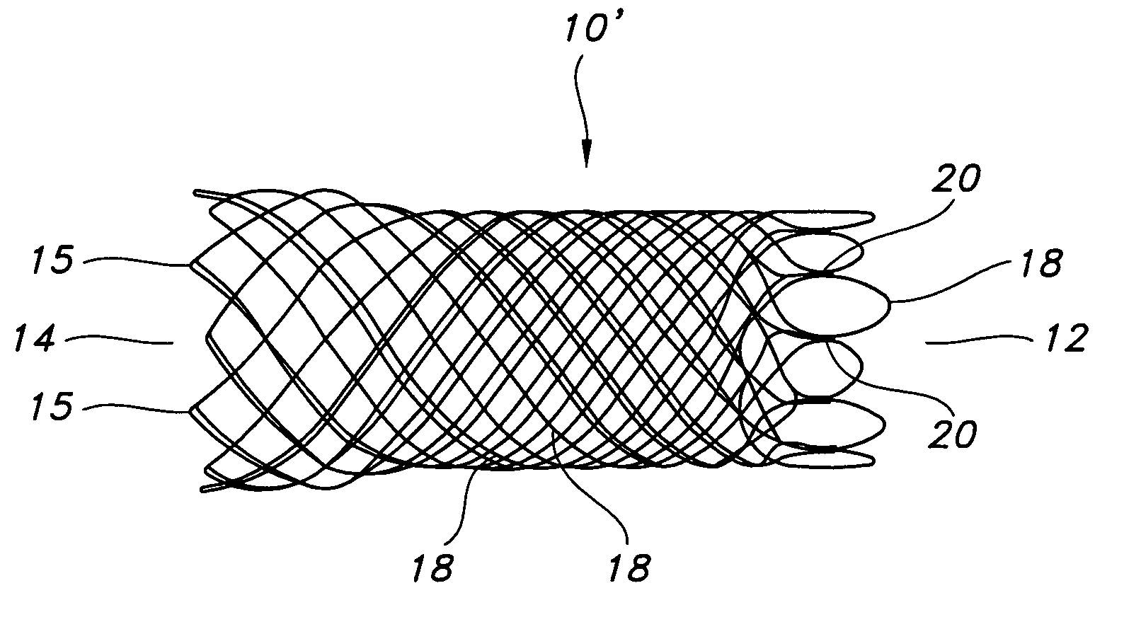
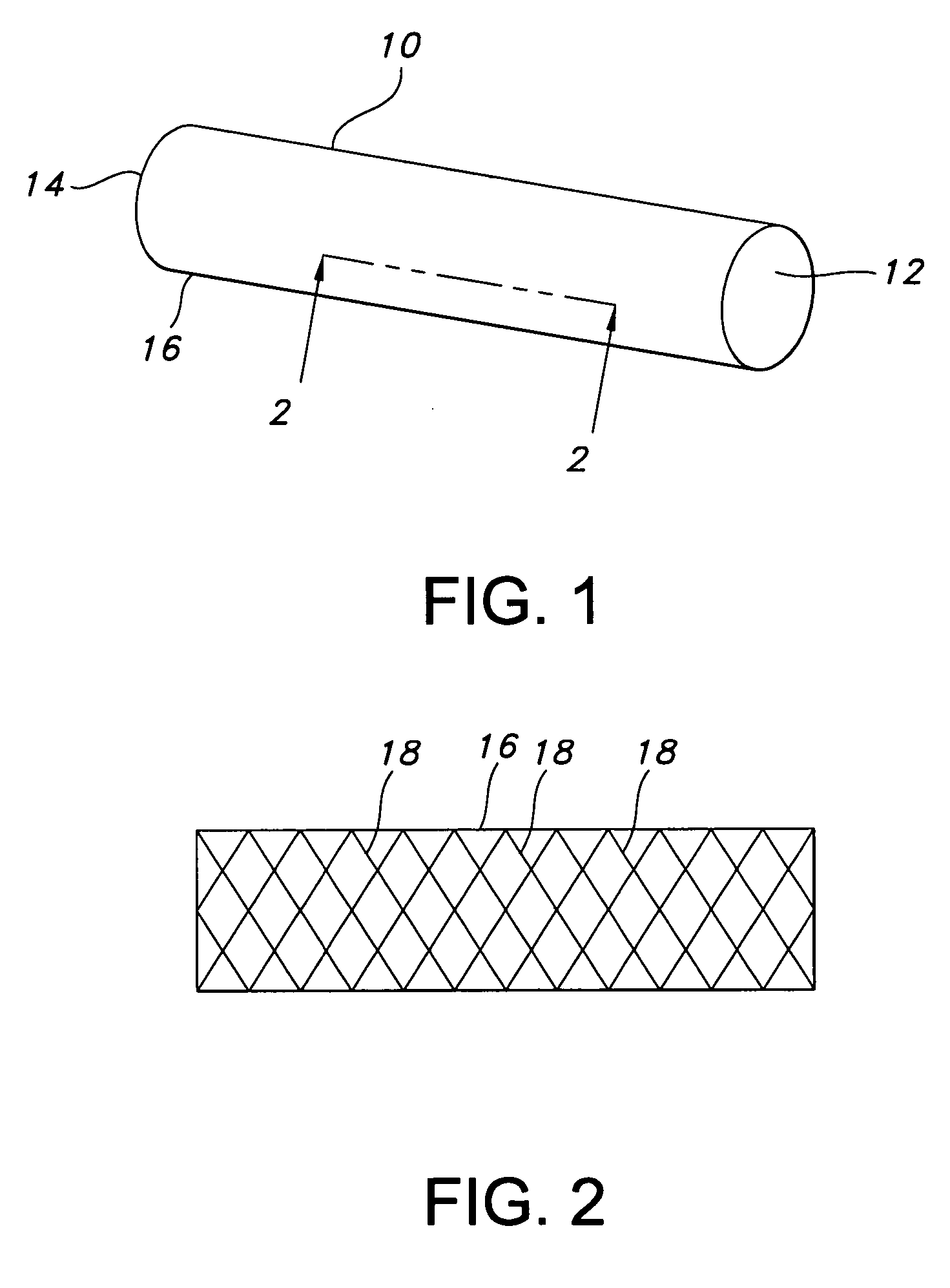
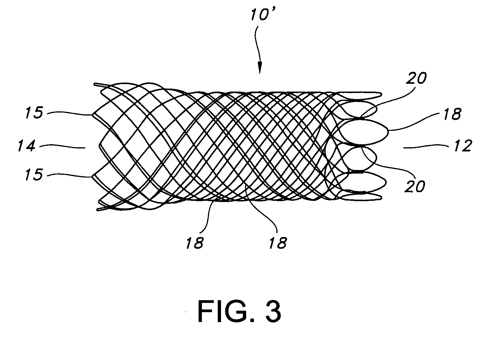
[0036]FIG. 1 depicts stent 10 of the present invention. Stent 10 is a hollow tubular structure having opposed open ends 12, 14 and having a tubular wall 16 therebetween. A portion of the tubular wall 16 is depicted in FIG. 2 as having a plurality of elongate wires 18 formed into the tubular wall 16. The elongate wires 18 traverse the length of the stent 10 in a direction traverse to the longitudinal length of the stent 10. The elongate wires 18 may be formed into the tubular wall 16 by braiding the wires 18, winding the wires 18, knitting the wires 18, and combinations thereof. Preferably, the wires 18 are braided to form the tubular wall 16.

[0037] As used herein the term braiding and its variants refer to the diagonal intersection of elongate filaments, such as elongate wires, so that each filament passes alternately over and under one or more of the other filaments, which is commonly referred to as an intersection repeat pattern. Useful braiding patterns include, but are not limi...


PUM

PropertyMeasurementUnit
Metallic bondaaaaaaaaaa
Radiopacityaaaaaaaaaa

Abstract

An implantable stent includes a plurality of elongate wires braided to form a hollow tubular structure having a tubular wall to define an interior surface and an exterior surface and having opposed open first and second ends, wherein the opposed open first and second ends are atraumatic ends The atraumatic ends of the stent are desirably free of any loose wire ends. The wires include composite wires to enhance visibility of the wires to provide improved external imaging of the wires in the body. The elongate composite wires of the stent may be metallic wires having an outer metallic portion including a first metal, such as nitinol, and an inner metallic core portion including a second metal, which is a radiopaque material, such as gold, barium sulfate, ferritic particles, platinum, platinum-tungsten, palladium, platinum-iridium, rhodium, tantalum or combinations thereof.

Description

CROSS-REFERENCE TO RELATED APPLICATIONS [0001] This application claims the benefit of U.S. Provisional Application No. 60 / 626,729, filed Nov. 10, 2004, and U.S. Provisional Application No. 60 / 680,630, filed May 13, 2005, the contents of both of which are incorporated herein by reference.FIELD OF THE INVENTION [0002] The present invention relates to a stent having atraumatic looped ends with smooth stent wire ends and improved stent wire welds. The present invention also relates to an apparatus for deploying and positioning the atraumatic stent. BACKGROUND OF THE INVENTION [0003] Stents made from interconnecting, often braiding, elongate wires may be made less traumatic, i.e., atraumatic, by closing the loose wire ends at the ends of the stents. The loose wire ends have typically been closed by mechanical means, for example by welding. Such mechanical means, however, often have sharp ends which may score the inside of a delivery system from which it is deployed or may also irritate b...

Claims


Application Information

Patent Timeline
IPC IPC(8): A61F2/06A61F2/90
CPCA61F2/90A61F2250/0039A61F2220/0058D04C1/06D10B2509/06A61F2250/0098D04C3/48D10B2101/20D04C1/02
Inventor NORTON, PAUL K.ZUPKOFSKA, MICHAELBRADY, PETERLEANNA, GARY J.CLERC, CLAUDE O.BERTOLINO, WILLIAMHANLEY, GRAINNE
Owner BOSTON SCI SCIMED INC
Why Eureka
Try Eureka