Screw compressor

a screw compressor and compressor technology, applied in the direction of machines/engines, liquid fuel engines, lighting and heating apparatus, etc., can solve the problems of screw rotor start-up, screw rotor failure, and inability to operate reliably

Active Publication Date: 2006-06-08
BITZER KUEHLMASCHINENBAU GMBH
View PDF17 Cites 14 Cited by
  • Summary
  • Abstract
  • Description
  • Claims
  • Application Information

AI Technical Summary

Benefits of technology

[0041] The advantage of this solution is to be seen in the fact that, as a result, it may be monitored whether the screw compressor is adequately supplied with lubricant since the difference in pressure is representative for the flow of lubricant through the lubricant filter, wherein a smaller drop in pressure results at the lubricant filter and this is reflected in the difference in pressure.
[0042] A particularly simple solution provides for the differential pressure detection element to detect the pressure of the lubricant in the line system in front of a filter member and behind the filter member of the lubricant filter.

Problems solved by technology

Screw compressors of this type are known from the state of the art but the problem with them is that when the screw compressors are switched off there is often the risk of lubricant continuing to run in them and, therefore, of this lubricant collecting in the screw rotor receiving means in the area of the screw rotors and, as a result, leading to problems when the screw rotors are started up.
They do, however, have the disadvantage that their operational functioning is not reliable.

Method used


Image

  • Screw compressor
  • Screw compressor
  • Screw compressor

Examples


Embodiment Construction

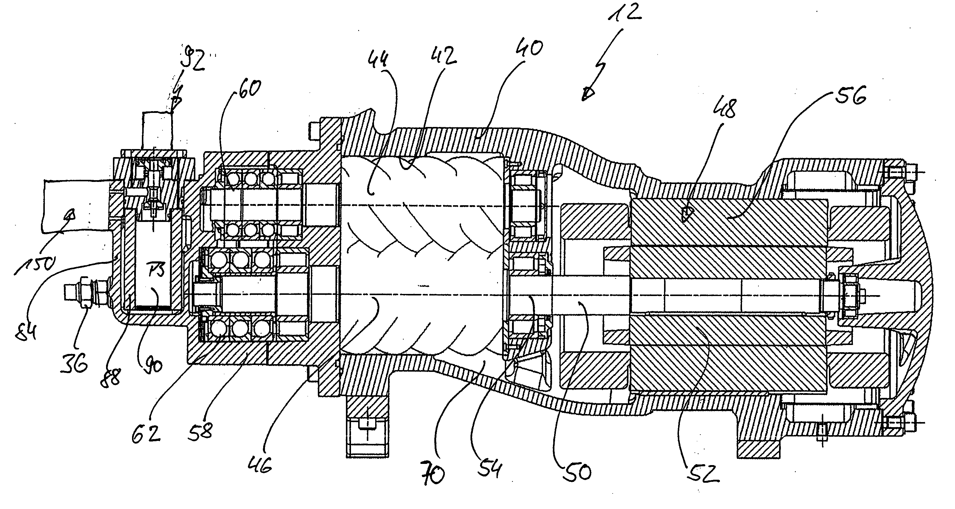
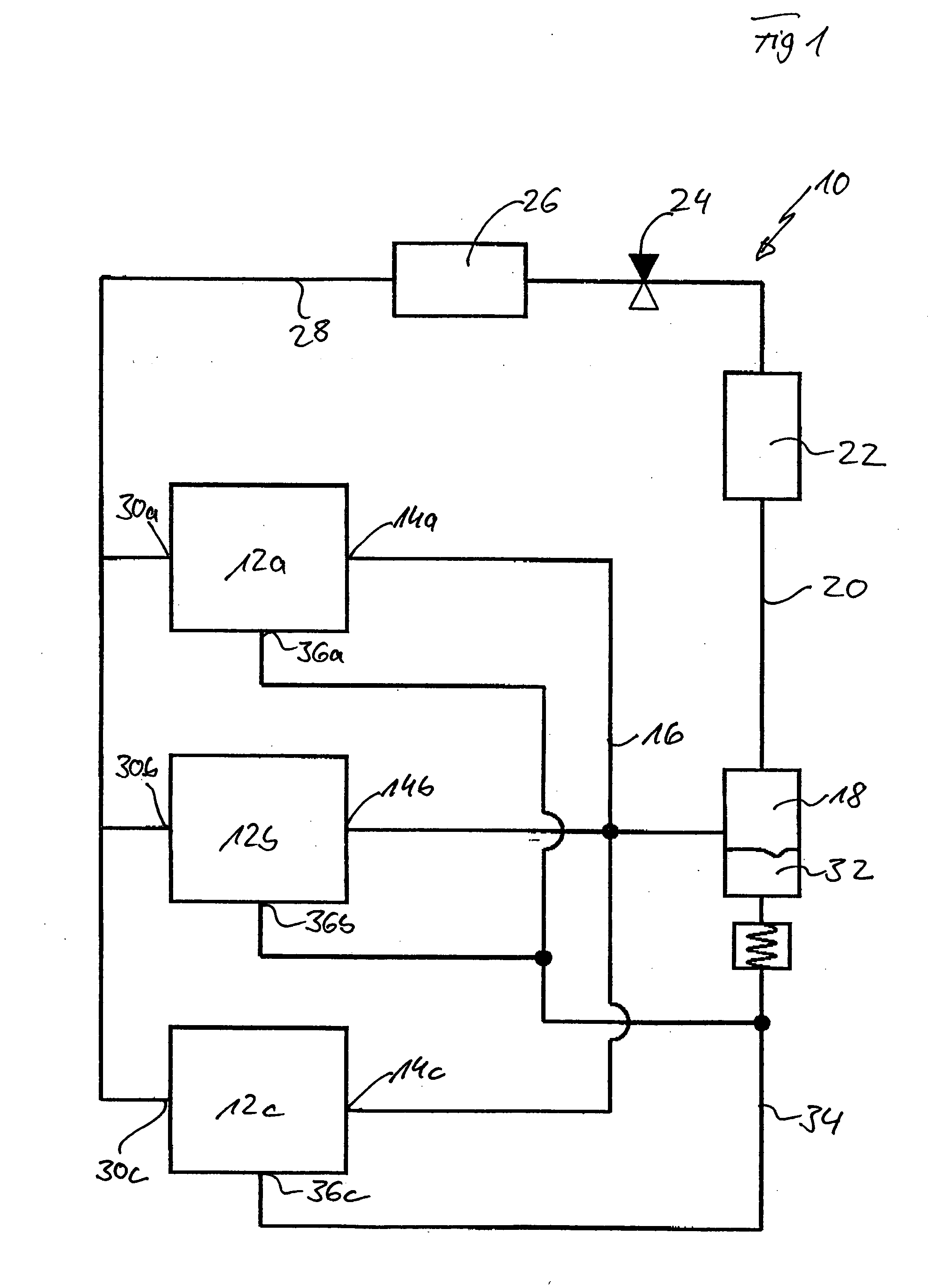
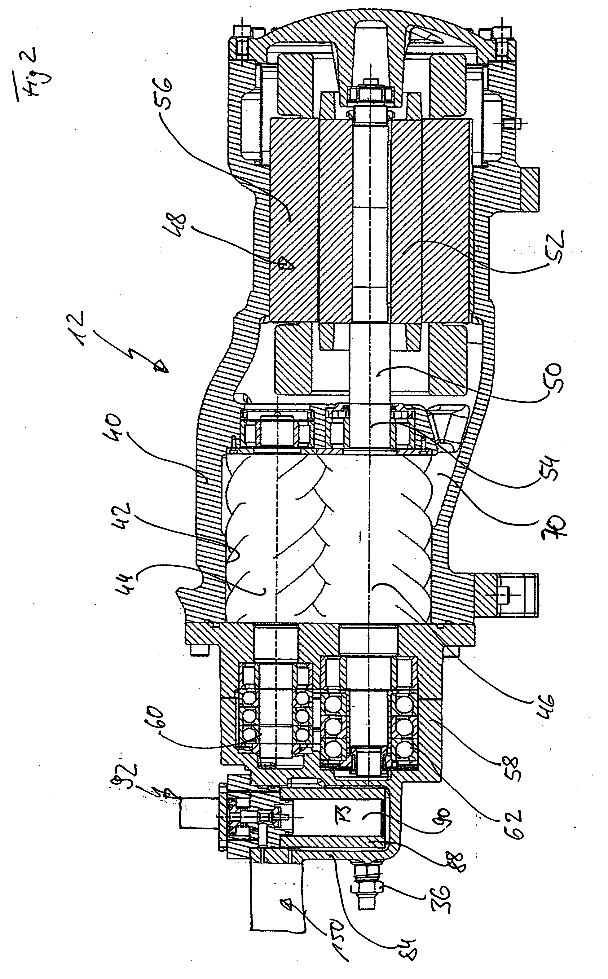
[0054] One embodiment of a refrigerant circuit according to the invention, designated in FIG. 1 as a whole as 10, comprises several compressors 12a to 12c connected in parallel, the high pressure connections 14a to 14c of which are connected to a high pressure line system 16 which leads into a lubricant separator which is designated as a whole as 18 and in which lubricant is separated from the refrigerant which is compressed and subject to high pressure.

[0055] A high pressure line 20 leads from the lubricant separator 18 through a heat exchanger 22 which cools the compressed refrigerant and then to an expansion valve 24 which serves the purpose of reducing the temperature of the refrigerant due to expansion thereof so that the expanded refrigerant has the possibility of releasing heat again in a heat exchanger 26.

[0056] In this respect, the expanded refrigerant is guided through a low pressure line 28 to low pressure connections 30a to c of the compressors 12a to c.

[0057] The com...


PUM


Abstract

In order to improve a screw compressor for compressing refrigerant in a refrigerant circuit, comprising a compressor housing, in which a screw rotor receiving means and an inlet channel as well as an outlet channel for the refrigerant to be compressed are provided, at least one screw rotor arranged in the screw rotor receiving means, a drive for the at least one screw rotor and a lubricant supply which conveys lubricant from a lubricant reservoir acted upon by pressure via a line system at least to the at least one screw rotor during operation, in such a manner that the operation and the monitoring of the screw compressor are reliable it is suggested that a valve be provided in the line system of the lubricant supply, this valve being controllable by way of a difference in pressure between the pressure in the outlet channel and a reference pressure influenced by a pressure in the refrigerant circuit and opening when the screw rotor is compressing refrigerant as well as closing when the screw rotor is not compressing refrigerant.

Description

[0001] This patent application claims the benefit of German Application No. 10 2004 060 596.3, filed Dec. 2, 2004, the teachings and disclosure of which are hereby incorporated in its entirety by reference thereto. BACKGROUND OF THE INVENTION [0002] The invention relates to a screw compressor for compressing refrigerant in a refrigerant circuit, comprising a compressor housing, in which a screw rotor receiving means and an inlet channel as well as an outlet channel for the refrigerant to be compressed are provided, at least one screw rotor arranged in the screw rotor receiving means, a drive for the at least one screw rotor and a lubricant supply which conveys lubricant from a lubricant reservoir acted upon by pressure via a line system at least to the at least one screw compressor during operation. [0003] Screw compressors of this type are known from the state of the art but the problem with them is that when the screw compressors are switched off there is often the risk of lubrica...

Claims


Application Information

Patent Timeline
Patent Type & Authority Applications(United States)
IPC IPC(8): F25B23/00
CPCF04C28/16F04C29/021F04C2240/81F04C2270/21Y10S418/01
Inventor DIETERICH, ROLF
Owner BITZER KUEHLMASCHINENBAU GMBH
Why Eureka
Try Eureka