Rear plate for plasma display panel

a plasma display panel and rear plate technology, applied in the direction of gas discharge electrodes, gas discharge vessels/containers, gas-filled discharge tubes, etc., can solve the problems of distorted barrier ribs, difficult to precisely locate each electrode on a central position, etc., and achieve the effect of improving reliability

Inactive Publication Date: 2006-06-08
LG MICRON
View PDF5 Cites 18 Cited by
  • Summary
  • Abstract
  • Description
  • Claims
  • Application Information

AI Technical Summary

Benefits of technology

[0009] In the rear plate, barrier ribs are formed through etching after backing, and thus the completed barrier ribs are not deformed. Therefore, each electrode can be exactly located on a central portion between barrier ribs. When a PDP having front and rear plates attached to each other has been completed, optical characteristics of the PDP such as white brightness, color temperature, and contrast, and electric characteristics of the PDP such as voltage margin, power consumption, and electric efficiency, are improved, so that the reliability is improved.

Problems solved by technology

As a result, in the course of the firing process, the barrier ribs may be distorted and deformed.
Therefore, it is difficult to exactly locate each electrode on a central position between two barrier ribs, which is a desired position for each electrode.

Method used


Image

  • Rear plate for plasma display panel
  • Rear plate for plasma display panel
  • Rear plate for plasma display panel

Examples


Embodiment Construction

[0014] Hereinafter, a rear plate of a plasma display panel according to a preferred embodiment of the present invention will be described in detail with reference to the accompanying drawings.

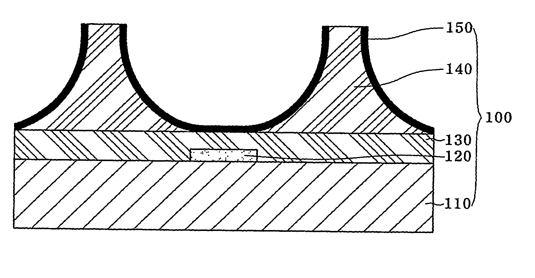
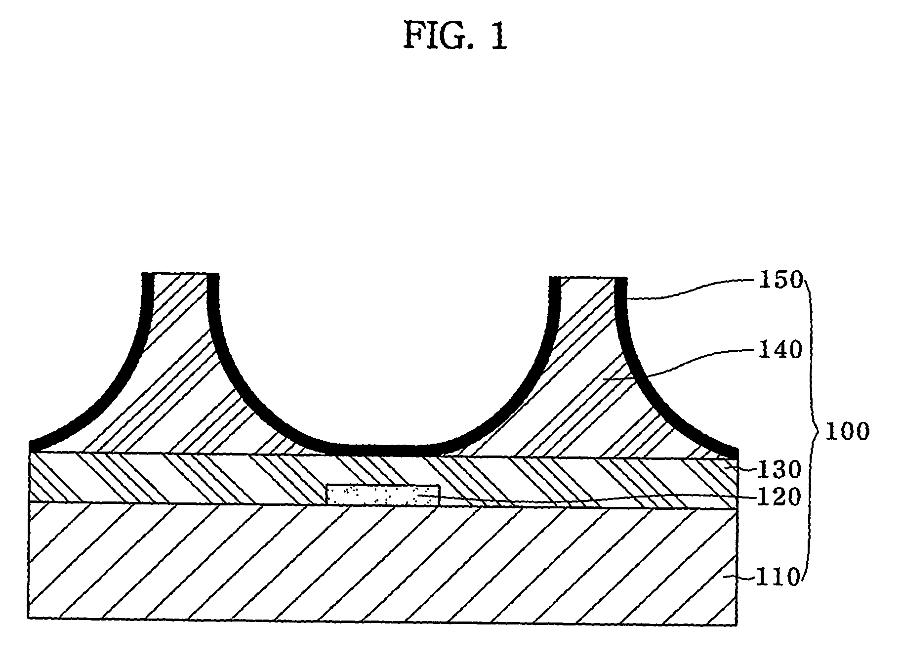
[0015] As shown in FIG. 1, a rear plate 100 of a plasma display panel (hereinafter, referred to as “PDP”) according to the present embodiment includes a glass substrate 110, electrodes 120 formed in a shape of a pattern and spaced at a predetermined interval from each other on an upper surface of the glass substrate 110, a dielectric layer 130 formed on upper surfaces of the electrode 120 and the upper surface of the glass substrate 110, barrier ribs 140 formed on an upper surface of the dielectric layer 130 and spaced a predetermined interval from each other, and phosphorous layers 150 formed on side surfaces and bottom surfaces of the barrier ribs 140.

[0016] A method of manufacturing the barrier rib 140 according to the present embodiment will be briefly described hereinafter. First, a proc...


PUM


Abstract

Disclosed is a rear plate of a plasma display panel. In the rear plate, barrier ribs are formed through etching after backing, and thus the completed barrier ribs are not deformed. Therefore, each electrode can be exactly located on a central portion between barrier ribs. When a PDP having front and rear plates attached to each other has been completed, optical characteristics of the PDP such as white brightness, color temperature, and contrast, and electric characteristics of the PDP such as voltage margin, power consumption, and electric efficiency, are improved, so that the reliability is improved.

Description

TECHNICAL FIELD [0001] The present invention relates to a rear plate of a plasma display panel. BACKGROUND ART [0002] As generally known in the art, a plasma display panel (PDP) is a display device having a front glass substrate and a rear glass substrate between which a discharge space is formed, so that plasma discharge may generate in the discharge space, thereby causing phosphors in the discharge space to be excited and emit light, so as to display a screen. [0003] PDPs may be classified into direct current plasma display panels (DC PDPs) and alternating current plasma display panels (AC PDPs), from among which the AC PDPs are the mainstream. U.S. Pat. No. 5,446,344 discloses a three-electrode surface-discharge alternating-current plasma display panel which is one of the representative AC PDPs. [0004] A PDP includes a front plate and a rear plate assembled in parallel with each other. The front plate includes a front glass substrate, transparent electrodes formed on a lower surf...

Claims


Application Information

Patent Timeline
Patent Type & Authority Applications(United States)
IPC IPC(8): H01J17/49H01J17/16
CPCH01J11/12H01J11/36H01J11/38H01J11/42H01J2211/225H01J2211/366H01J11/22
Inventor CHO, WON-DUK
Owner LG MICRON
Why Eureka
Try Eureka