System and method for the measurement of the velocity and acceleration of objects

a technology of velocity and acceleration, applied in the field of measurement systems and methods, can solve the problems of reducing the effect of disturbance, affecting the accuracy of measurement, so as to reduce the effect of disturbance and accurate measuremen

Inactive Publication Date: 2006-06-08
OMNITEK PARTNERS LLC
View PDF9 Cites 13 Cited by
  • Summary
  • Abstract
  • Description
  • Claims
  • Application Information

AI Technical Summary

Benefits of technology

[0014] According to one aspect of the invention, only two surface features are sufficient to determine the average velocity of the object relative to the plane of reference in any direction for objects undergoing planar motion and for linear motion of an object rotating about a fixed axis. Similarly, only three surface features are sufficient to measure the average linear acceleration of the object relative to the pl

Problems solved by technology

All existing prior art approaches, however, suffer from one or more of the following disadvantages: (1) a number of such devices can only measure linear velocity and/or acceleration.
In many cases, this may not be feasible due to space or weight considerations, or may not be economical to mount such relatively expensive devices on the object; (3) the measuring sensors and their related instrumentations that hav

Method used


Image

  • System and method for the measurement of the velocity and acceleration of objects
  • System and method for the measurement of the velocity and acceleration of objects
  • System and method for the measurement of the velocity and acceleration of objects

Examples


first embodiment

I. FIRST EMBODIMENT

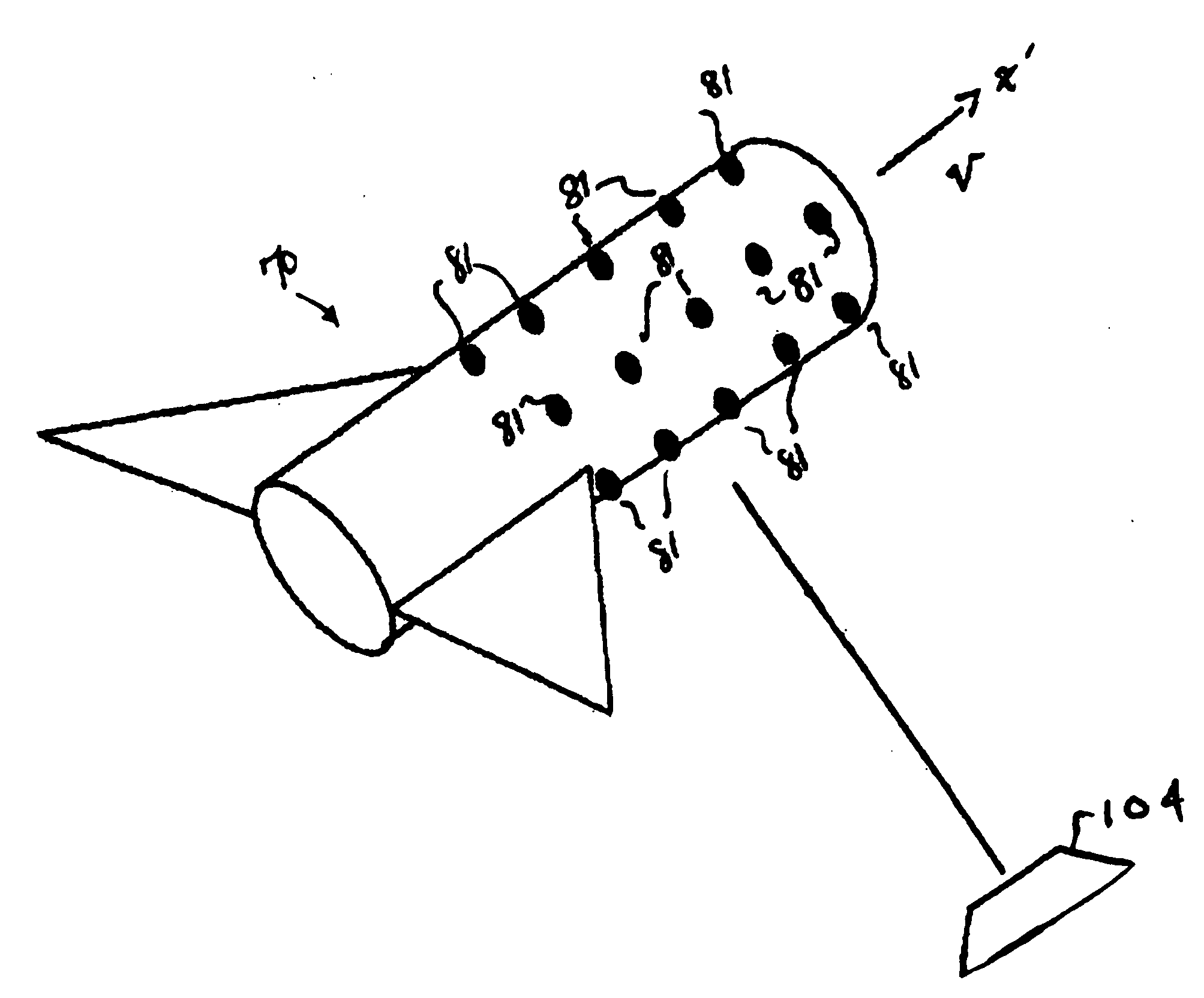
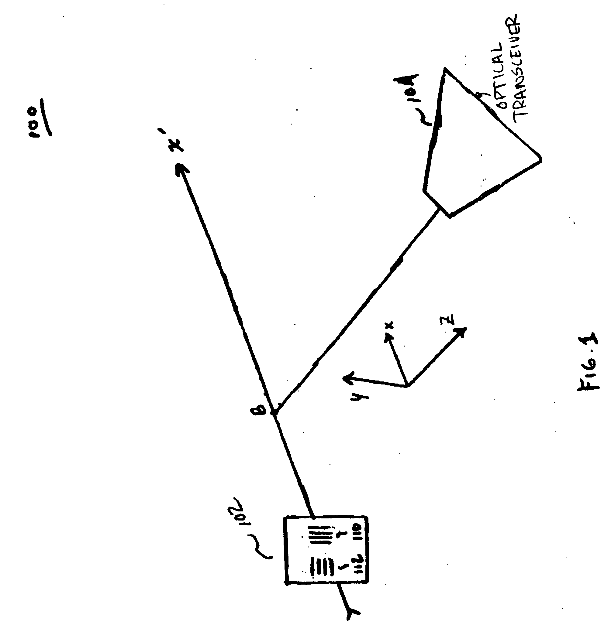
[0039] With reference now to FIG. 3, one embodiment of the present invention is directed to the measurement of the position, instantaneous linear velocity VL and instantaneous linear acceleration AL of an essentially cylindrical object 30 that is traveling along a linear path X′ while rotating about its longitudinal axis of symmetry (in this case the line X′), as well as the measurement of its instantaneous angular velocity VR about the line X′.

[0040] The first step in making a position and a time-of-flight measurement of an object 30 is to prepare the object 30 by applying (i.e., painting, etching, etc.) a plurality of linear velocity measurement lines 33 and a plurality of angular velocity measurement lines 34 to the surface of the object 30. As shown in FIG. 3, linear velocity measurement lines 33 are applied perpendicular to the direction of linear motion X′. Angular velocity measurement lines 34 are applied parallel to the direction of linear motion X′. It s...

second embodiment

II. SECOND EMBODIMENT

[0049] In the second embodiment, alternative surface features are illustrated which can be used to measure both linear and rotational velocity of a cylindrical object translating parallel and rotating about its centerline.

[0050] The success of the present embodiment depends upon the application of appropriate combination of surface features to the object 30. The present embodiment will be described with reference to FIGS. 4a-b. In all the cases presented for the present embodiment,

[0051] With reference first to FIG. 4a, the object 30 is first prepared or modified by applying a surface feature in the form of an equilateral triangle 43, and lines 44a-c and lines 44d-f to the surface of the object 30 to measure the linear velocity VL and rotational velocity VR of the object. As shown, the measurement lines consist of a centrally positioned equal sided triangle 43 and two sets of measurement lines 44a-c, 44d-f. As shown, measurement lines 44a-c are positioned to o...

third embodiment

III. THIRD EMBODIMENT

[0067] The third embodiment is directed to determining the linear and rotary position, velocity and acceleration of an object of arbitrary shape undergoing planar motion.

[0068] With reference now to FIG. 5, object 60 is considered to be undergoing a planar motion. The Cartesian XYZ coordinate system is fixed to the object 60. The planar motion of the object 60 is considered to be parallel to the XY plane of the XYZ coordinate system.

[0069] In the first case of this embodiment, the object 60 is considered to be undergoing a linear translation. Without the loss of generality, the linear motion of the object 60 is considered to be parallel to the direction of the X-axis of the XYZ coordinate system.

[0070] A shown in FIG. 5, there are shown a plurality of equally spaced parallel lines 62 on the surface of object 60. The lines 62 may or may not be perpendicular to the path of motion, i.e., perpendicular to the X-axis. The linear velocity V65 relative to a referenc...


PUM


Abstract

A method and system is disclosed for determining a flight characteristic of an object in a flight path, the flight characteristic to be determined can be the object's position while in flight, a linear velocity, a rotational velocity or an acceleration of the object. In one embodiment, the method comprises arranging a radiation source in a plane, the plane being located to intersect the flight path of the object. The radiation source irradiates the object at least at the intersection with the flight path. The object is provided with at least first and second surface features having a predetermined configuration such as, for example, equally spaced parallel lines painted on the surface of the object. Reflected radiation from the object is measured with a sensor from the surface features and a flight characteristic of the object is determined based on the measured reflected radiation and the predetermined configuration of the surface features.

Description

BACKGROUND OF THE INVENTION [0001] 1. Field of the Invention [0002] The present invention relates generally to measurement systems and methods, and more particularly to a system and an associated method for making time-of-flight non-contact optical measurements of the velocity and acceleration of objects. [0003] 2. Description of the Prior Art [0004] In the prior art, many applications require knowledge of the speed (i.e., linear and / or rotational velocity) and acceleration of an object that is traveling in a specified direction at one or more points along its path of motion. This occurs, for example, in the case of an object moving on an assembly line or in the case of a cylindrical object that moves along its longitudinal axis in a tube or is launched through such a tube. [0005] Various methods for the measurement of velocity and acceleration of an object with respect to a reference system exist. One measuring method described in the prior art includes the use of inertial sensors ...

Claims


Application Information

Patent Timeline
IPC IPC(8): G01C3/08G01P3/36
CPCG01P3/36G01P3/486G01P3/50G01P3/68G01P15/16G01P15/165
Inventor RASTEGAR, JAHANGIR S.DHADWAL, HARBANS
Owner OMNITEK PARTNERS LLC
Why Eureka
Try Eureka