Magnetic disk drive with flying height control system

Inactive Publication Date: 2006-06-08
WESTERN DIGITAL TECH INC
View PDF12 Cites 66 Cited by
  • Summary
  • Abstract
  • Description
  • Claims
  • Application Information

AI Technical Summary

Benefits of technology

[0019] According to the present invention, it is possible to provide a control method capable of keeping a constant distance between a read/write element and a magnetic disk without the necessity of making the m

Problems solved by technology

If the flying height of the magnetic head slider is excessively reduced, the magnetic head slider contacts the magnetic disk and vibrates due to frictional force.
If the magnetic head slider vibrates, it is difficult to perform stable read/write operation.
In addition, the slider's protective film and the disk's protective film are worn by the frictional force.
If these protective films are worn away, the magnetic films of the magnetic head and disk may suffer corrosion, electric discharge, etc., posing a significant problem in the reliability of the magnetic disk drive.
If the temperature falls, the vicinity of the read/write element retreats away from the recording surface of the magnetic disk, which may make it impossible to perform stable read/write operation.
It

Method used


Image

  • Magnetic disk drive with flying height control system
  • Magnetic disk drive with flying height control system
  • Magnetic disk drive with flying height control system

Examples


Embodiment Construction

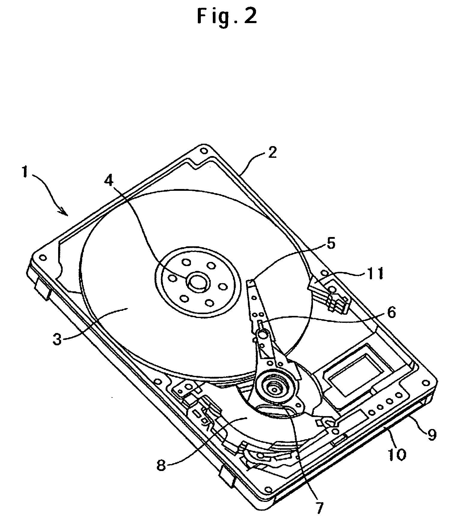
[0028]FIG. 2 schematically depicts the configuration of a magnetic disk drive according to an embodiment of the present invention. FIG. 3 is its block diagram including the control system. The magnetic disk drive 1 has a base 2 to form the enclosure, a cover (not shown in the figure) and a control circuit board 9 attached to the back side of the base 2. In FIG. 2, the cover is removed. Magnetic information is stored on a magnetic disk 3 which is rotated by a spindle motor 4 fixed on the base 2. Held and pressed toward the magnetic disk 3 by a suspension 6, a magnetic head slider 5 flies low above the magnetic disk 3 due to a flow of air generated by the rotating magnetic disk 3. When a seek operation is done to position the magnetic head slider 5 for read / write on the recording surface of the magnetic disk 3, the magnetic head slider 5 is moved in the radial direction of the magnetic disk 3 together with the suspension 6 by an actuator 7 which is driven by a voice coil motor (VCM) 8...


PUM


Abstract

Embodiments of the invention appropriately control the flying height of a magnetic head slider as necessary without making the magnetic head slider touch the magnetic disk. In one embodiment, when a magnetic disk drive is started, the level of electric power predefined for the ordinary temperature (room temperature) is read in from the internal memory of an MPU. A temperature sensor measures the internal temperature of the magnetic disk drive and sends it to the MPU. According to the temperature sent from the temperature sensor, the MPU calculates the level of electric power which should be applied to a flying height adjustment structure. According to the calculated electric power, the MPU increases or decreases the electric power applied to the flying height adjustment structure. At a flying height controlled (corrected) by the flying height adjustment structure, a magnetic head slider performs read/write on a magnetic disk.

Description

CROSS-REFERENCES TO RELATED APPLICATIONS [0001] This application claims priority from Japanese Patent Application No. JP2004-354000, filed Dec. 7, 2004, the entire disclosure of which is incorporated herein by reference. BACKGROUND OF THE INVENTION [0002] The present invention relates to magnetic disk drives and more particularly to a method for controlling the flying height of a magnetic head slider. [0003] To raise recording densities in magnetic disk drives and consequently realize higher storage capacity and more compact drives, efforts have been made to reduce the flying height as a major means. The flying height is defined as the distance between the magnetic head slider and the magnetic disk. Reducing the distance between the read / write element and the magnetic disk's recording surface makes it possible to raise the linear recording density in the direction of rotation of the magnetic disk. [0004] There have been prior techniques to reliably reduce the flying height of a magn...

Claims


Application Information

Patent Timeline
IPC IPC(8): G11B21/02G11B19/02
CPCG11B5/6005G11B5/6064G11B5/607G11B5/6082
Inventor YAMAZAKI, TAKANORITANAKA, HIDEAKIKURITA, MASAYUKI
Owner WESTERN DIGITAL TECH INC
Why Eureka
Try Eureka