Receiver with baseline wander compensation

a baseline and receiver technology, applied in the direction of dc level restoring means or bias distorting correction, gain control, baseband system details, etc., can solve the problems of increasing the bit error at the receiver end of the transmission system, causing data errors, and affecting the resolution of the receiver, so as to effectively enhance resolution without increasing the bit number of the ad

Active Publication Date: 2006-06-08
RDC SEMICON CO LTD
View PDF5 Cites 25 Cited by
  • Summary
  • Abstract
  • Description
  • Claims
  • Application Information

AI Technical Summary

Benefits of technology

[0009] In light of the above and other drawbacks, an objective of the present invention is to provide a receiver with baseline wander compensation applicable to a network transmission system, so as to prevent occurrence of data error due to baseline wander interference to the receiver of the network transmission system, and to effectively enhance resolution without increasing bit number of the ADC.
[0012] Therefore, the receiver with baseline wander compensation is subjected to dynamic adjustment via the analog and digital gain stage originally available in the system. With cooperation of the digital baseline wander compensator, the receiver of the network transmission system prevents occurrence of data error due to baseline wander interference. And the resolution is effectively enhanced without increasing bit number of the ADC, thereby reducing bit error of the system.

Problems solved by technology

That is, a baseline wander effect is produced to increase the bit error at the receiver end of the transmission system.
Thus, it is a major issue of a network transmission industry to eliminate occurrence of the baseline wander in the transmission system.
However, such baseline wander correction circuit still contains several drawbacks.
Therefore, it is a current issue for the transmission system to prevent baseline wander interference without affecting the resolution of the ADC at the same time.

Method used


Image

  • Receiver with baseline wander compensation
  • Receiver with baseline wander compensation
  • Receiver with baseline wander compensation

Examples


Embodiment Construction

[0019] The present invention is described below with specific embodiments, so that one skilled in the pertinent art can easily understand other advantages and effects of the present invention from the disclosure of the invention. The present invention may also be implemented and applied according to other embodiments, and the details may be modified based on different views and applications without departing from the spirit of the invention.

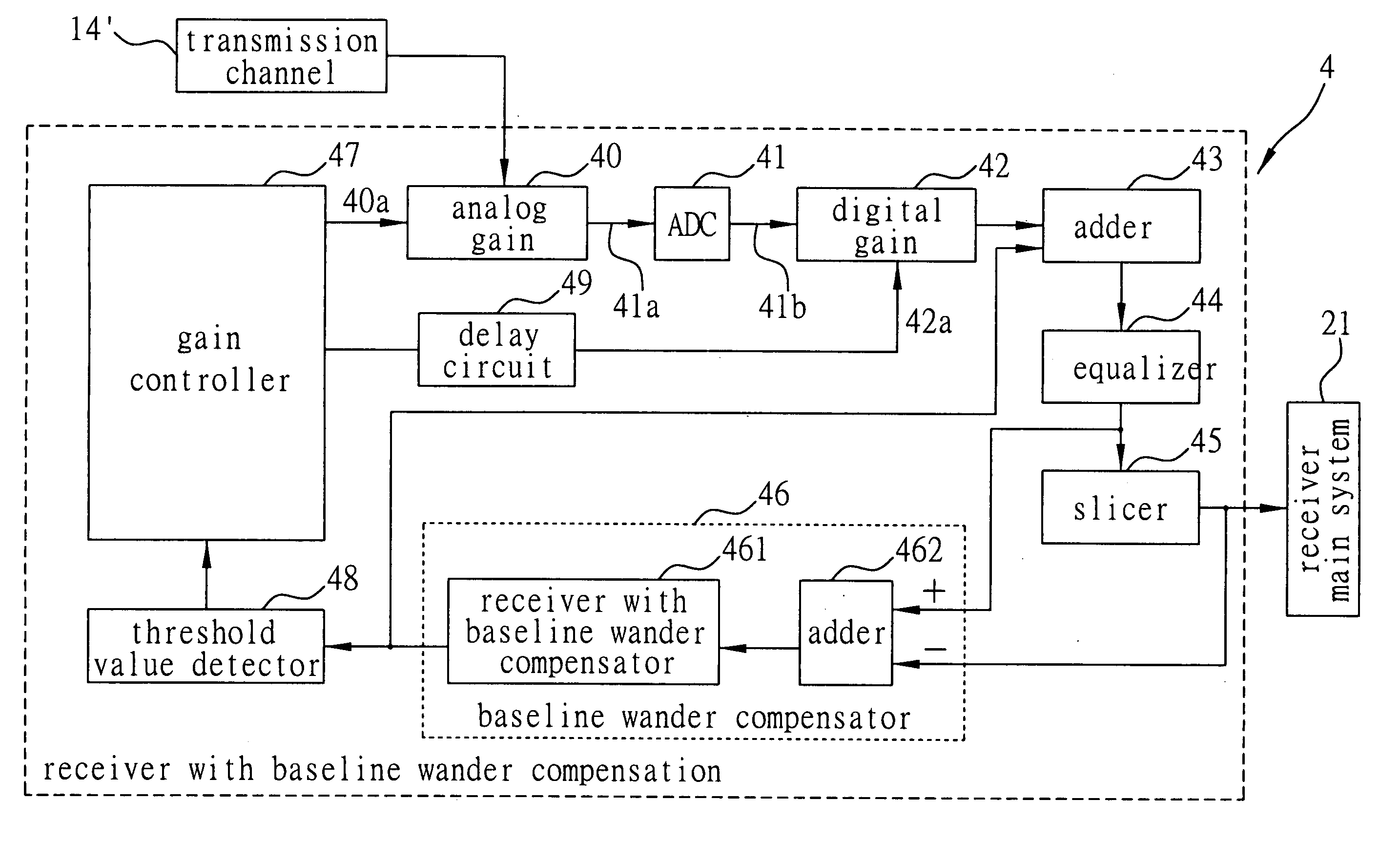
[0020]FIG. 3 is a schematic diagram illustrating a basic architecture of a receiver with baseline wander compensation according to the present invention. The receiver 4 with the baseline wander compensation receives transmission data (that is, communication signals) from a transmitter of an Ethernet via a transmission channel 14′ such as a twisted-pair wire, optical cable, coaxial cable, or other appropriate transmission interfaces. The received transmission data is then subjected to signal conversion by an Analog-to-Digital Converter (ADC) 41, ...


PUM


Abstract

A receiver with baseline wander compensation is applicable to a digital communication system. The receiver includes an Analog-to-Digital Converter (ADC), a slicer, a threshold value detector, a gain controller, a baseline wander compensator, a delay circuit, an analog gain stage, and a digital gain stage. The baseline wander compensator is used to perform an operation and a filtering process on a voltage obtained prior to processing by the slicer and a voltage after the processing so as to obtain a baseline wander voltage value for compensation and control. The threshold value detector and the gain controller dynamically produce control signals of analog gain and digital gain. The analog gain stage compensates degrading of communication signals passing through transmission channels in an analog gain manner. The delay circuit is used to compensate the delay of the conversion performed by the ADC. The digital gain stage compensates insufficiency of the analog gain.

Description

BACKGROUND OF THE INVENTION [0001] 1. Field of the Invention [0002] The invention relates to compensating devices, and more particularly, to a receiver with baseline wander compensation applicable to a network system, such as Ethernet to prevent baseline wander interference. [0003] 2. Description of the Related Art [0004] When data is transmitted between main systems of two ends via Ethernet, a transmission system is served as a transmission medium. As illustrated in FIG. 1, the transmission system includes a transmitter 10, a sending coupler 12, a transmission channel 14, a receiving coupler 13 and a receiver 11, such that a receiver main system 21 receives signal from a transmitter main system 20 via the transmission system. [0005] The transmission channel 14 of the transmission system includes a transmission interface such as a twisted-pair wire, an optical fiber or a coaxial cable. Since the sending coupler 12 and the receiving coupler 13 are electrically insulated devices, dama...

Claims


Application Information

Patent Timeline
Patent Type & Authority Applications(United States)
IPC IPC(8): H04L27/08
CPCH03G3/3089H04L25/063
Inventor YEN, MING-CHOUTSAI, KUN-YINGKO, JUI-TAIWEI, CHUN-WANG
Owner RDC SEMICON CO LTD
Why Eureka
Try Eureka