Reducing discomfort caused by electrical stimulation

a technology of electrical stimulation and pain, which is applied in the field of electrical stimulation, can solve the problems of patient discomfort at the stimulation site, the difficulty of direct access to the spinal cord, and the inability to achieve satisfactory relief of depression symptoms, so as to reduce discomfort and reduce the effect of transcutaneous stimulation

Active Publication Date: 2006-06-08
NEURONETICS
View PDF99 Cites 85 Cited by
  • Summary
  • Abstract
  • Description
  • Claims
  • Application Information

AI Technical Summary

Problems solved by technology

The spinal cord is difficult to access directly because vertebrae surround it.
Yet many patients remain without satisfactory relief from the symptoms of depression.
To date, ECT remains the “gold standard” of treatments for severe depression; however, many patients will not undergo the procedure because of its severe side effects.
However, one reported side effect of rTMS for the treatment of depression is patient discomfort at the site of the stimulation.
This discomfort is caused, in part, by the depolarization of neuron membranes in the scalp and the resulting scalp muscle contractions that occur at the frequency of the rTMS.
Testing has shown that approximately 25% of rTMS patients report this discomfort to be at a level that is very uncomfortable.
In general, the greater the power and the higher the frequency of the therapeutic magnetic stimulation, the more discomfort is reported.
Yet, reducing the power levels may not be a viable option because greater power has been shown to desirably stimulate deeper structures.

Method used


Image

  • Reducing discomfort caused by electrical stimulation
  • Reducing discomfort caused by electrical stimulation
  • Reducing discomfort caused by electrical stimulation

Examples


Embodiment Construction

[0029] Overview

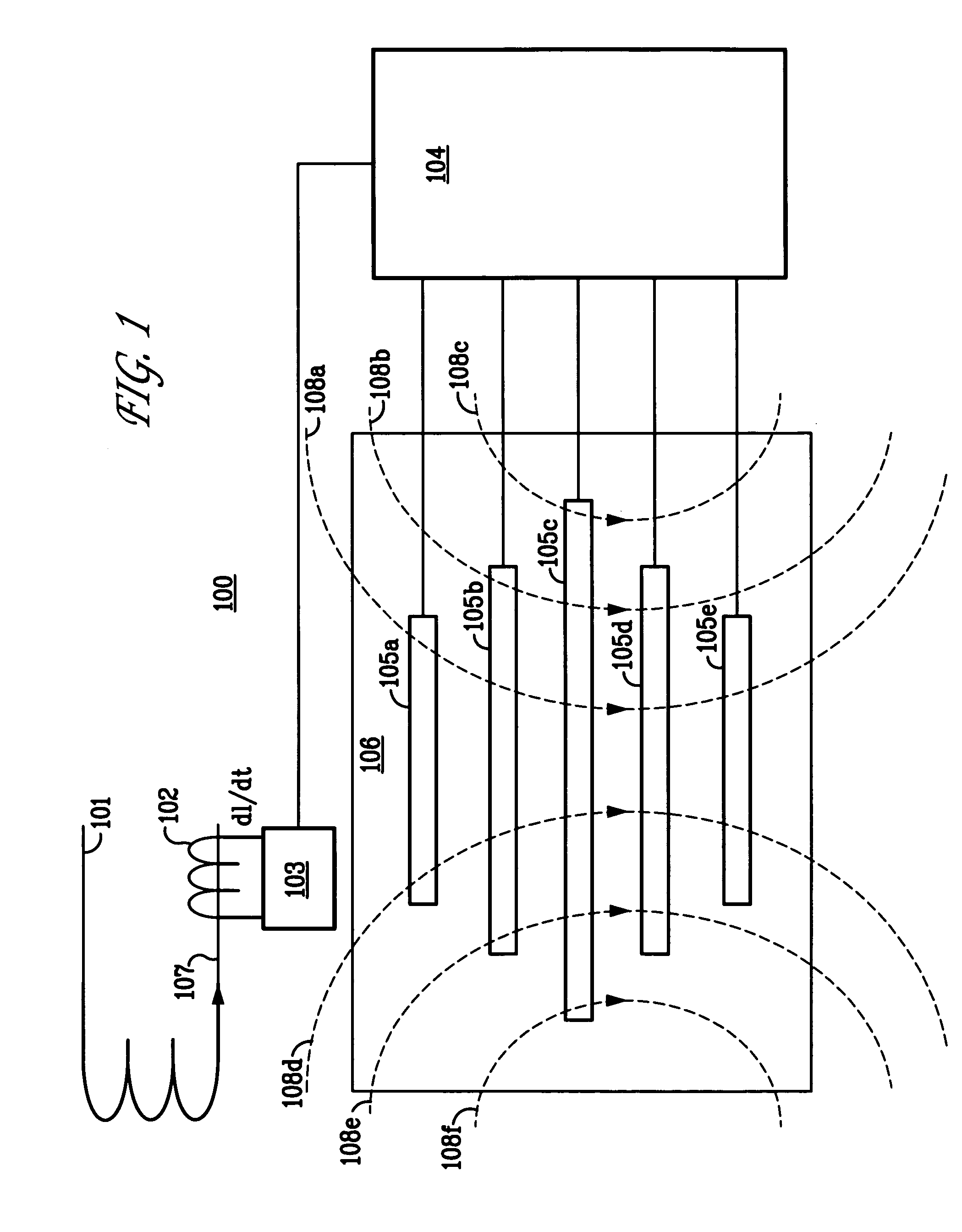
[0030] In 1831, Michael Faraday discovered that the magnitude of an electric field induced on a conductor is proportional to the rate of change of magnetic flux density that cuts across the conductor. Faraday's law, well known to those skilled in the art may be represented as E˜−(dB / dt), where E is the induced electric field in volts / meter, dB / dt is the time rate of change of magnetic flux density in Tesla / second. In other words, the amount of electric field induced in an object like a conductor is determined by two factors: the magnetic flux density and the time rate of change of the flux density. The greater the flux density and its derivative, the greater the induced electric field and resulting current density. Because the magnetic flux density decreases in strength as the square of the distance from the source of the magnetic field, the flux density is greater the closer the conductor is to the source of the magnetic field. When the conductor is a coil, the curr...


PUM


Abstract

The invention is directed to a novel method for reducing discomfort caused by transcutaneous stimulation. The novel method includes providing transcutaneous stimulation, reducing the transcutaneous stimulation at a first location, and substantially maintaining the transcutaneous stimulation at a second location. The transcutaneous stimulation may be created by electric and / or magnetic fields. The first location may be relatively proximate to the cutaneous surface and may comprise tissue, nerves and muscle. Also, the second location may be relatively deeper than the first location and include, for example, brain tissue that requires the transcutaneous stimulation for treatment purposes. The invention further may include locating a conductor on a treatment area and / or a transcutaneous stimulation device relative to the first location. In addition, the method may further include adjusting how much the transcutaneous stimulation is reduced at the first location.

Description

CROSS-REFERENCE TO RELATED APPLICATION [0001] This application claims priority under 35 U.S.C. § 119 (e) from U.S. provisional application Ser. No. 60 / 452,477, filed on Mar. 7, 2003, entitled “Device, Method, and System for the Reduction of Discomfort Associated with and Facilitating Treatment via Magnetic Stimulation,” which is herein incorporated by reference in its entirety. This application is a continuation-in-part of U.S. patent application Ser. No. 10 / 657,296 (Attorney Docket No. NNI-0002), filed Sep. 8, 2003 entitled “Reducing Discomfort Caused by Electrical Stimulation,” which is herein incorporated by reference in its entirety.FIELD OF THE INVENTION [0002] The invention relates to the field of electrical stimulation. Specifically, the invention relates to reducing discomfort created by electrical stimulation. BACKGROUND OF THE INVENTION [0003] A number of medical ailments are treated or treatable through the application of electrical stimulation to an afflicted portion of ...

Claims


Application Information

Patent Timeline
Patent Type & Authority Applications(United States)
IPC IPC(8): A61N2/00
CPCA61N1/36025A61N2/004A61N2/06A61N2/008A61N2/02A61N2/006
Inventor RIEHL, MARK EDWARDGHIRON, KENNETH MARC
Owner NEURONETICS
Why Eureka
Try Eureka