Adjustable holder for cleaning implement

a technology of cleaning implements and adjustable brackets, which is applied in the direction of cleaning machines, manufacturing tools, carpet cleaners, etc., can solve the problems of material breakage and difficulty in adjusting the position of the holder, and achieve the effect of low production and assembly costs

Inactive Publication Date: 2006-06-15
SC JOHNSON & SON INC
View PDF16 Cites 31 Cited by
  • Summary
  • Abstract
  • Description
  • Claims
  • Application Information

AI Technical Summary

Benefits of technology

[0019] When the device is used, it is preferred that a sleeve-like cleaning mitt be mounted over a forked portion of the support head so that all tines of the fork are within the sleeve. The support head tines are, in this configuration, thus capable of being fully enclosed by the mitt, avoiding the possibility of the fork scratching delicate furniture or other items being contacted.
[0020] Embodiments of the present invention therefore achieve many of the desired functionalities found in existing dusters (e.g. capability of replacing the cleaning head after a single use; a single product which can dust mop a floor or furniture; a dust mop capable of angular adjustment relative to the main handle; relatively low production and assembly costs). However, they also achieve other desirable functionalities in various embodiments.

Problems solved by technology

Note that if the threshold is set above 1.4 Newton meters of torque some consumers may have difficulty adjusting the positions of the holder, and there may be some instances of material breakage as some consumers apply too much force when trying to cause the adjustment.

Method used


Image

  • Adjustable holder for cleaning implement
  • Adjustable holder for cleaning implement
  • Adjustable holder for cleaning implement

Examples


Embodiment Construction

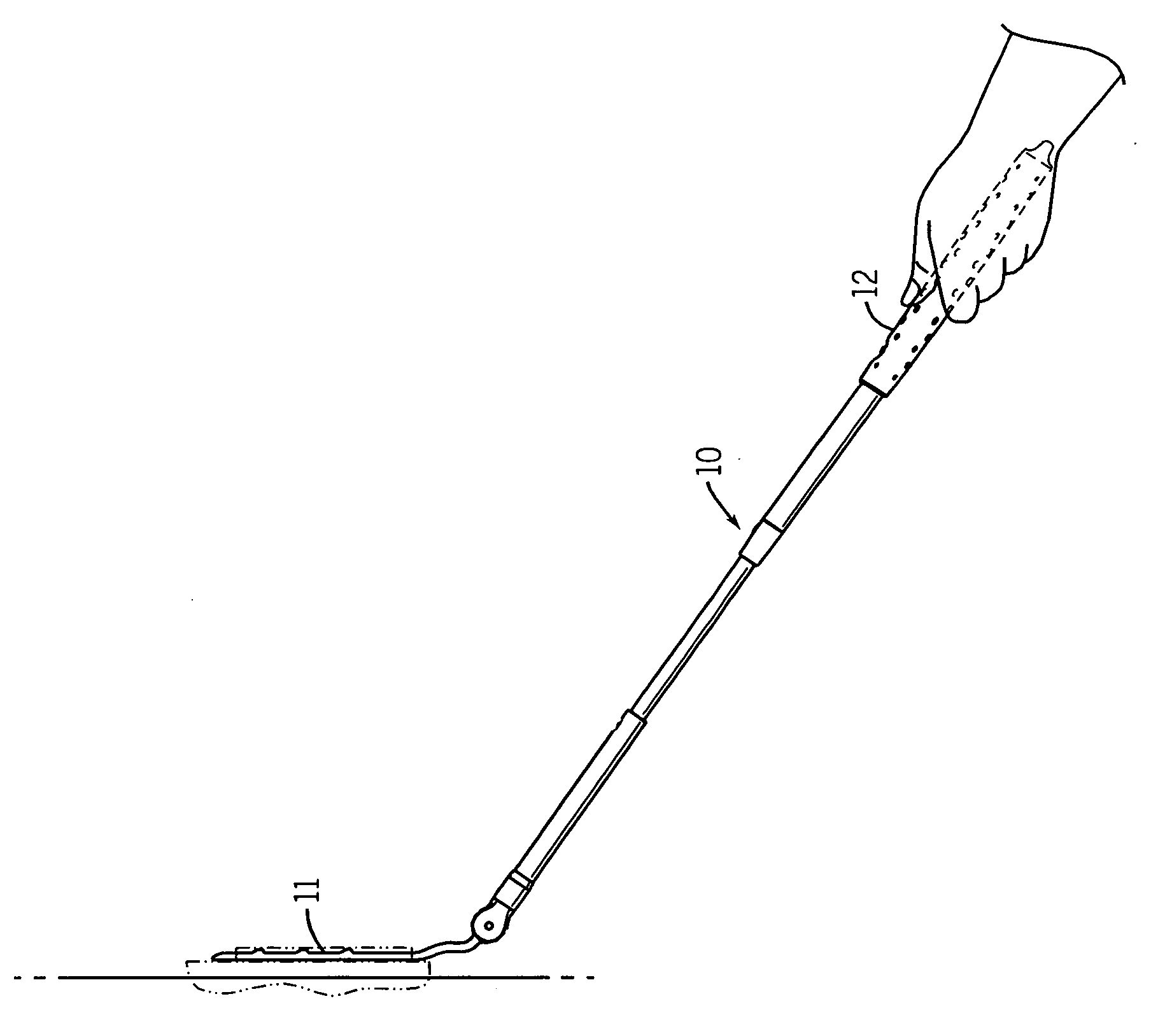
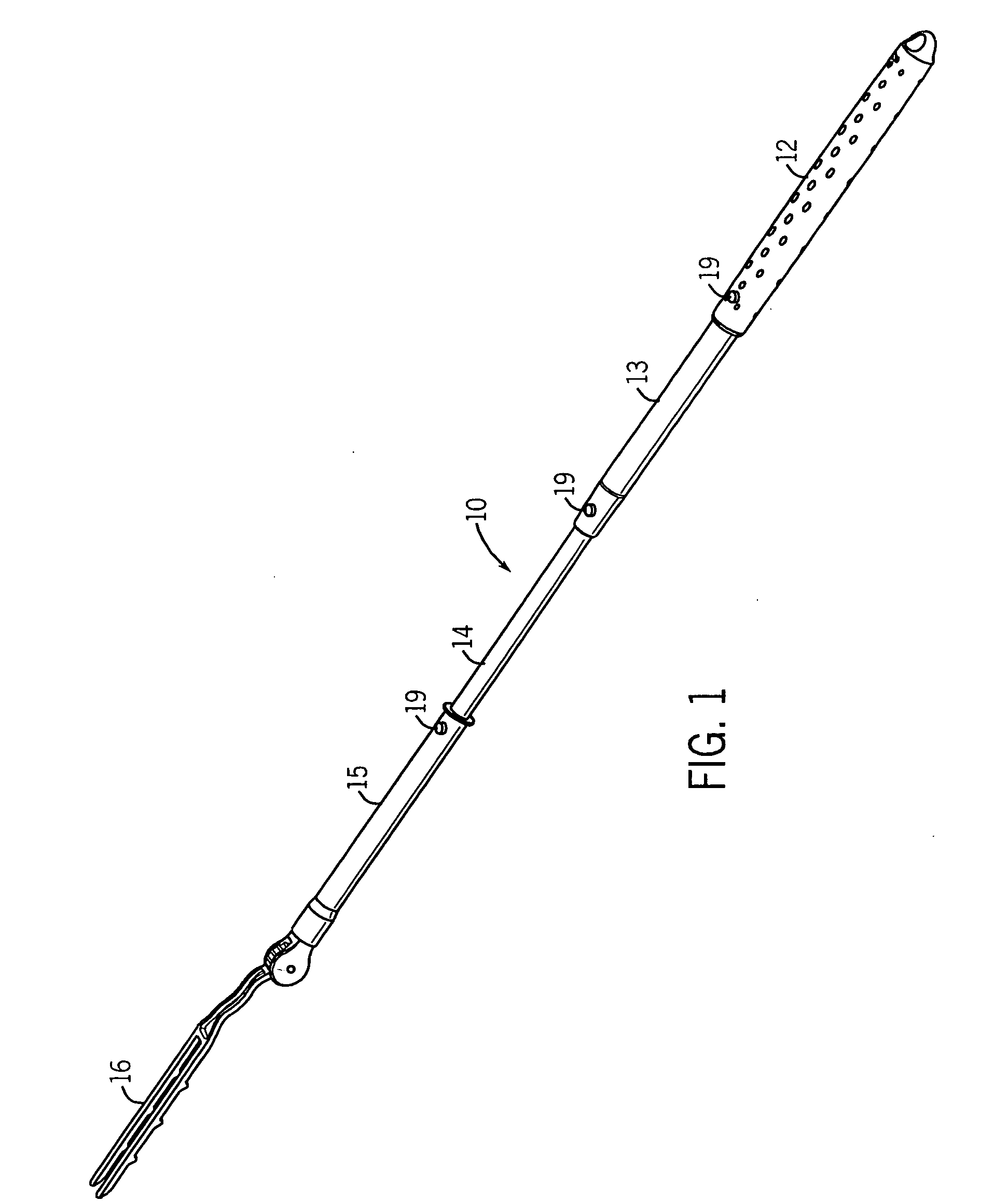
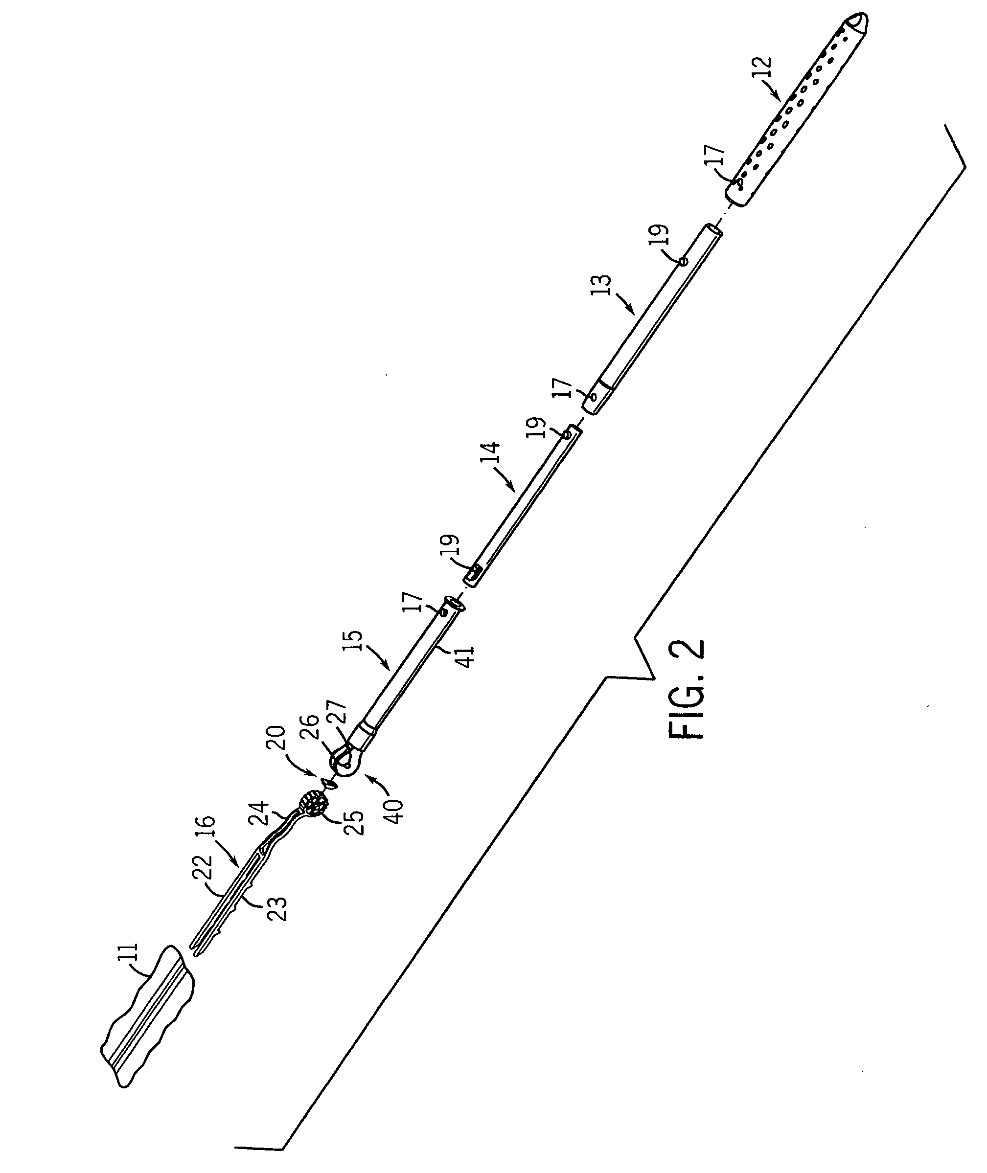
[0032] As best seen in FIGS. 1 and 2, there is shown a holder 10 designed to be used with a cleaning implement / replaceable dusting sleeve / cleaning mitt 11. The holder has a grip 12, telescoping handle extension pieces 13 and 14, shank 15 and support head 16. There is also a resilient catch 20.

[0033] In this preferred form various radially extending bumps 19 are formed on some of these parts which fit into corresponding catch holes 17 on adjacent parts. While not shown in detail, these bumps 19 are preferred to be positioned on flexible tabs which can deflect radially inwardly as the tubular parts are assembled to one another, and then flex radially outwardly into the holes 17 to temporarily fix the tubular parts in the FIG. 1 position.

[0034] One can then press the bump 19 of extension part 13 radially inward to permit extension part 13 to telescope into a hollow of handle grip 12. Similarly, the bump 19 on the rear end of extension part 14 can be pressed radially inward to permit ...


PUM

PropertyMeasurementUnit
torqueaaaaaaaaaa
torqueaaaaaaaaaa
torqueaaaaaaaaaa

Abstract

A dusting device is disclosed. There is a telescoping handle, a shank mountable to the handle, and a supporting fork mounted to the shank for relative rotation with respect thereto. A cleaning sleeve is replaceably mountable on the fork for single use dusting purposes. The angle of the fork with respect to the telescoping handle can be releasably fixed by a catch mechanism. While the catch is sufficiently strong to resist angle adjustment during normal dusting, it permits the angle to be adjusted by firmly pressing the end of the fork (with or without the sleeve thereon) against a wall while holding the distal end of the telescoping handle. This converts the duster from a wall duster, to a duster capable of cleaning the tops of ceiling fan blades, without the need for a consumer to touch a portion of the device near the duster head. In another aspect the device has two such adjustable forks for holding two such sleeves which can be used simultaneously.

Description

CROSS-REFERENCE TO RELATED APPLICATIONS [0001] Not applicable. STATEMENT REGARDING FEDERALLY SPONSORED RESEARCH / DEVELOPMENT [0002] Not applicable. BACKGROUND OF THE INVENTION [0003] The present invention relates to cleaning devices such as hand dusters and dust mops. More particularly, it relates to devices of this type having a replaceable cleaning implement, preferably a telescoping handle, and an adjustable support head for mounting the cleaning implement relative to the handle at various angles. [0004] It is well known to clean dust and dirt from floors, furniture, or other room surfaces by rubbing a dust rag against the surface, such that the dust and dirt adhere to the cloth. Sometimes this cleaning is facilitated by wetting the rag with water, a polish or other liquid. Such cloths or strips thereof have on occasion also been mounted on a head of a cleaning implement, which in turn is affixed to an elongated handle, to thereby create a floor dust mop. See e.g. U.S. Pat. No. 2,...

Claims


Application Information

Patent Timeline
Patent Type & Authority Applications(United States)
IPC IPC(8): A47L13/20
CPCA47L13/24A47L13/42
Inventor MALONEY, MICHAEL J.ASKLING, KEVIN L.FENSKE, LAWRENCE J.FALENDYSZ, GREGORY
Owner SC JOHNSON & SON INC
Why Eureka
Try Eureka