Illuminated indicia

a technology of indicia and indicia, applied in the field of illuminated indicia, can solve the problems of inability to sharpen the corners of the indicia, break down with partial failure, and inability to meet the needs of small indicia,

Inactive Publication Date: 2006-06-15
ARVIN HOSSEIN
View PDF23 Cites 11 Cited by
  • Summary
  • Abstract
  • Description
  • Claims
  • Application Information

AI Technical Summary

Benefits of technology

[0017] It is a further object of the invention to provide devices to create illuminated indicia formed from a material containing a light stimulating agent or additive and capable of absorbing light and transmitting it to an exposed edge to form a halo effect and distinctive aesthetics of the indicia at the exposed edge.
[0018] Thus in accordance with the present invention there is provided an illuminated indicia formed from a material capable of absorbing light and transmitting light to an exposed edge. The material is preferably a fluorescent plastic material such as fluorescent acrylic sheets or molded members. The indicia has a li...

Problems solved by technology

There are several problems with neon signs.
They can break down with partial failure while power is still on.
They are not practical for small in...

Method used


Image

  • Illuminated indicia
  • Illuminated indicia
  • Illuminated indicia

Examples


second embodiment

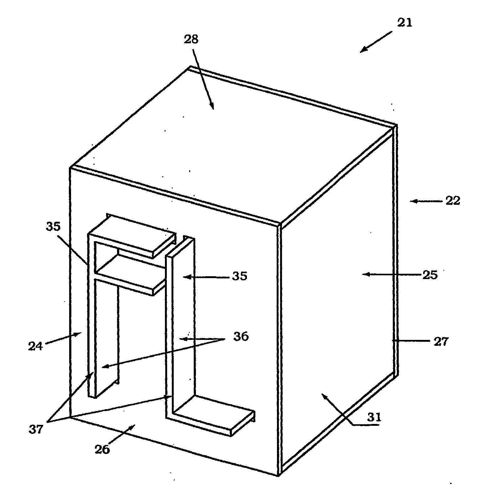
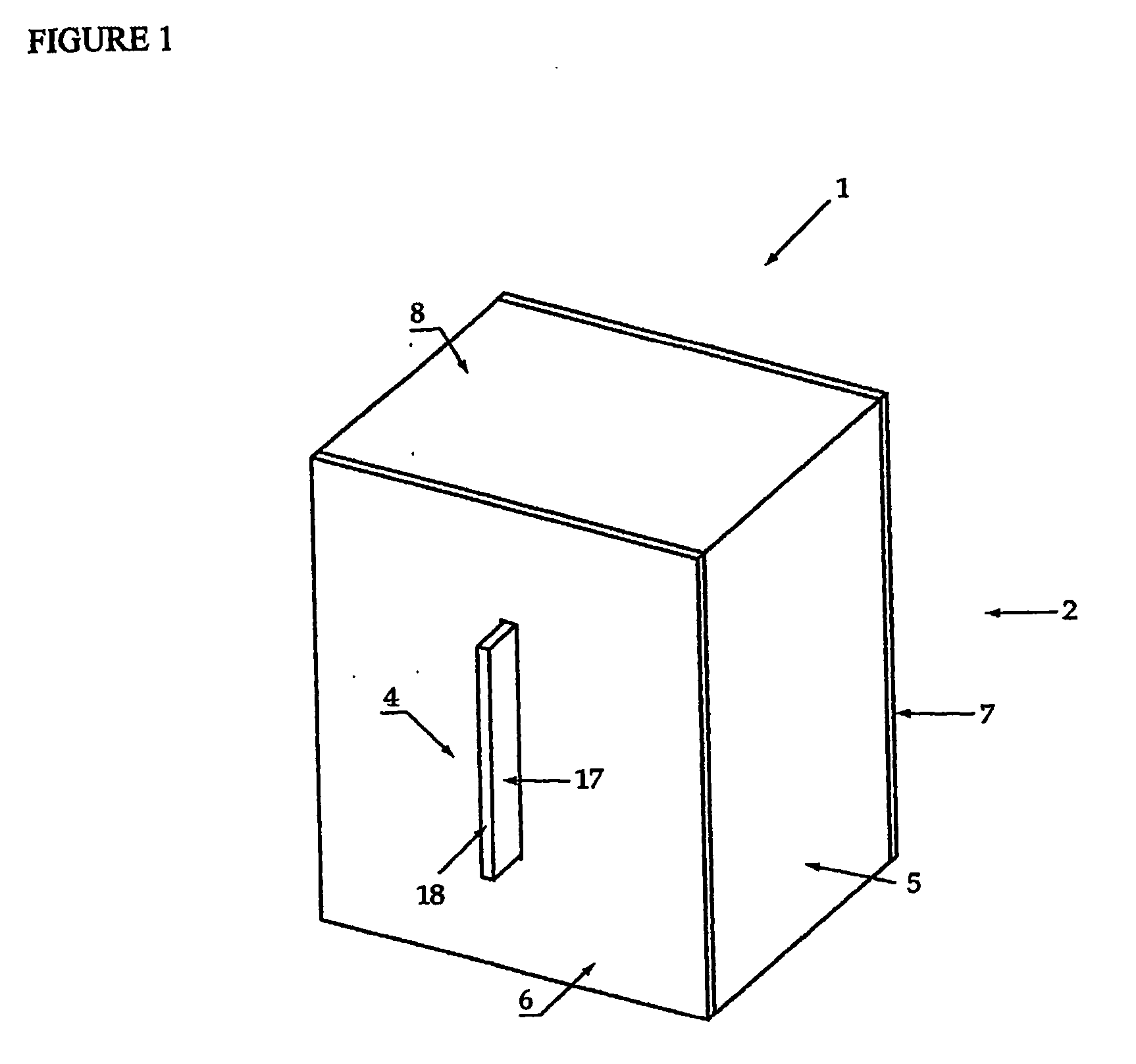
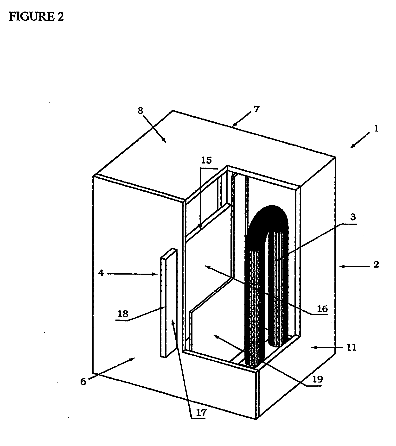
[0036]FIGS. 5 and 6 show a device 21 to create an illuminated indicia according to the present invention using surrounding natural or artificial light. The device comprises a chamber 22 and indicia 24. The chamber 22, in the embodiment illustrated, is a rectangular box 25 having front 26, back 27, top 28, bottom 29 and opposite side 30, 31 panels. The front panel 26 and back panel 27 are made of a clear transparent material. The preferred material is transparent acrylic sheet with high transmitting properties. Other options include clear glass, clear polystyrene, clear polycarbonate or polyvinyl chloride. The front and back panels 26, 27 can be eliminated if the indicia 24 can be suspended in a stable position within chamber 22 for example with wires or the like. The side panels 30, 31 are optionally made from a material preferably with reflective internal surface 34 or any other material with similar qualities. The top panel 28 and bottom panel 29 are similarly made from an opaque ...

third embodiment

[0039] Referring to FIGS. 7 to 8, a device to create an illuminated indicia according to the present invention is generally indicated at 61. In this embodiment the indicia is illuminated by light from the front of the indicia. The device consists of a chamber 62 and indicia 64. The chamber 62, in the embodiment illustrated, is a rectangular box 65 having front 66, back 67, top 68, bottom 69 and opposite side 70, 71 panels. The front panel 66 is made of any transparent material. The preferred material is transparent acrylic sheet with high transmitting properties. Other options include clear glass, clear polystyrene, clear polycarbonate or polyvinyl chloride. The back panel 67 is preferably is made from an opaque material preferably with a reflective internal surface 72 or any other material with similar qualities. Suitable materials for the back panel 67 are acrylic mirror, stainless steel, chrome-plated plastics such as ABS or chrome plated aluminum etc. The side panels 70, 71 are ...


PUM


Abstract

The present invention relates to an illuminated indicia (4) formed from a material capable of absorbing light and transmitting light to an exposed edge. The material is preferably a fluorescent plastic material such as fluorescent acrylic sheets or molded members. The indicia (4) has a light absorbing section and a display section. The light absorbing section is exposed to a light source and the absorbed light is transmitted to the exposed edge (18) of the display section. The thickness of the exposed edge (18) of the display section is less than the length of the light absorbing section. Under typical indoor and outdoor lighting conditions, a constant passive illumination is created by the exposed edge of the display section. In a preferred embodiment the indicia is formed from material containing a light stimulating agent or additive. When the intensity of the light is sufficient, a halo effect may be achieved at the exposed edge.

Description

BACKGROUND OF THE INVENTION [0001] 1. Field of the Invention [0002] This invention relates to devices to create illuminated indicia with distinctive illumination aesthetics of the indicia. The present invention has particular application to illuminated signs. [0003] 2. Description of the Prior Art [0004] Traditionally illuminated indicia have been created by various means, including neon signs or remote lighting such as flood lighting or by backlighting. [0005] There are several problems with neon signs. They can break down with partial failure while power is still on. You must use external coloring on the tube to achieve different colors in one system. They are not practical for small indicia. With the power source switched off, neon signs are virtually indecipherable. With neon signs, sharp corners on the indicia cannot be made. Neon signs are either “on” or “off”. [0006] Similar problems exist with both remote lighting, floodlighting and backlit signs. [0007] Other methods of dis...

Claims


Application Information

Patent Timeline
IPC IPC(8): G09F13/00G09F13/02G09F13/04G09F13/20
CPCG09F13/02G09F13/0404G09F13/0413G09F13/20
Inventor ARVIN, HOSSEIN
Owner ARVIN HOSSEIN
Why Eureka
Try Eureka