Cooling of milk in an automatic milking system

a technology of automatic milking and milk cooling, which is applied in the field of dairy farming, can solve the problems of sluggish temperature response, large risk of cooling milk, and sluggish response, and achieve the effect of not exposing to risk the milk freezing

Inactive Publication Date: 2006-06-15
DELAVAL HLDG AB
View PDF5 Cites 4 Cited by
  • Summary
  • Abstract
  • Description
  • Claims
  • Application Information

AI Technical Summary

Benefits of technology

[0006] An object of the present invention is to provide a method and an arrangement, respectively for cooling milk rapidly in an automatic milking system without risk of freezing the milk, particularly when only small amounts of milk are present in the milk storage tank.

Problems solved by technology

It is necessary to be careful during cooling of the milk since the quality is deteriorated if the milk freezes.
When the milk storage tank only contains small amounts of milk, there is a considerable risk of cooling the milk too much since the cooling device, when cooling, operates at full capacity.
The milk temperature is usually measured on the outside of the tank due to hygienic requirements, and this results in a rather slow response when the temperature of the milk within the tank is changed.
Such a sluggish temperature response gives rise to problems, in particular when the volume of stored milk is small.
The temperature of a small milk volume is lowered rapidly at the risk of freezing the milk.
Such a stirrer is usually not able to stir the milk in the tank when the tank contains only small amounts of milk, which thus involves a further risk of freezing milk locally at the beginning of the filling of the tank with milk.
If cooling, on the other hand, is omitted while there is only a small volume of milk in the milk storage tank, this milk is not cooled at once, and thus the quality of the milk is deteriorated.

Method used


Image

  • Cooling of milk in an automatic milking system
  • Cooling of milk in an automatic milking system
  • Cooling of milk in an automatic milking system

Examples


Embodiment Construction

[0016] In the following description, for purpose of explanation and not limitation, specific details are set forth, such as particular techniques and applications in order to provide a thorough understanding of the present invention. However, it will be apparent for a person skilled in the art that the present invention may be practiced in other embodiments that depart from these specific details.

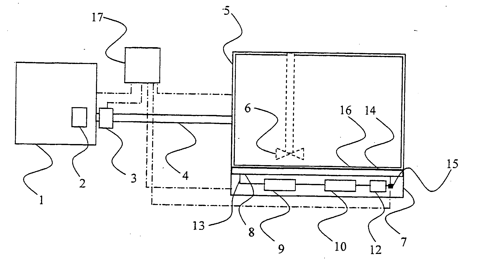
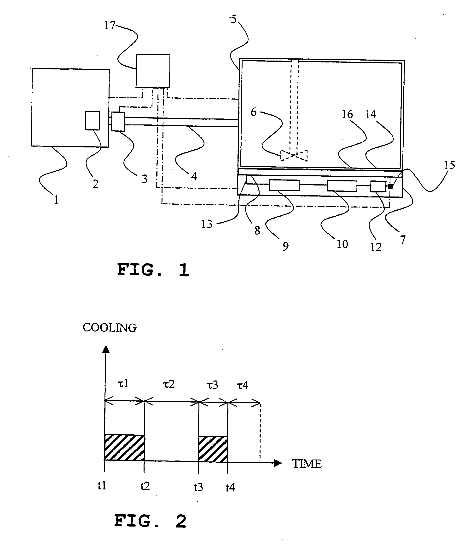
[0017] An automatic milking system, as shown in FIG. 1, comprises a milking robot 1 for milking animals, such as cows, including a milk flow meter 2 for measuring the milk flow during milking; a milk storage tank 5 which stores milk for collection on a regular time basis; a milk line 4 connecting the milking robot 1 with the milk storage tank 5; a milk pump (not shown) for pumping milk from the milking robot 1 to the milk storage tank 5; and a pre-cooling device 3 for cooling milk, which is pumped over to the milk storage tank 5.

[0018] The milk storage tank 5 is provided with a stirrer 6 ...


PUM


Abstract

The present invention relates to a method for cooling milk in a milk storage tank of an automatic milling system comprising the steps of (i) measuring an amount of extracted milk by means of a milk flow meter, (ii) determining a cooling need for milk stored or to be stored in said milk storage tank based on said amount of milk; (iii) measuring a quantity indicative of a temperature of an inner surface area of a bottom portion of the milk storage tank; and cooling said bottom portion of said milk storage tank in consecutive periods, such that each period of cooling (τ1, τ3) is followed by a respective period of non-cooling (τ2, τ4), wherein the duration of each period of cooling and/or noncooling is based on said measured quantity indicative of said inner surface area temperature, and said cooling need. The invention also relates to an arrangement for performing the method.

Description

FIELD OF INVENTION [0001] The present invention relates generally to dairy farming and particularly to a method and an arrangement, respectively, for cooling of milk in an automatic milking system. BACKGROUND [0002] In dairy farming animals are milked and their milk is thereafter stored in a milk storage tank for collection on a regular time basis, e.g. every second day. In order to maintain the quality of the milk, it is cooled to approximately 4° C. as quickly as possible. It is necessary to be careful during cooling of the milk since the quality is deteriorated if the milk freezes. [0003] At a dairy farm provided with an automatic milking system, the milk usually enters the milk storage tank in small amounts spread during the day and night, compared to a dairy farm without an automatic milking system, where all animals are milked together two or three times a day. The milk storage tank is usually equipped with a cooling device, which lowers the temperature of the milk to about 4°...

Claims


Application Information

Patent Timeline
Patent Type & Authority Applications(United States)
IPC IPC(8): A01J3/00A01J5/00A01J5/017A01J9/04
CPCA01J5/0175F25B2700/197F25B2600/0251A01J9/04
Inventor LIDMAN, MAGNUSPERSSON, STAFFAN
Owner DELAVAL HLDG AB
Why Eureka
Try Eureka