
Connection of two coaxially in-line elements in a fuel supply system of an internal combustion engine

a fuel supply system and internal combustion engine technology, applied in the direction of liquid fuel feeders low-pressure fuel injection, etc., can solve problems such as complete failure of these components, and achieve the effect of reducing material stresses

Inactive Publication Date: 2006-06-15
SCHOEFFLER JOCHEN
View PDF10 Cites 8 Cited by
  • Summary
  • Abstract
  • Description
  • Claims
  • Application Information

AI Technical Summary

Benefits of technology

"The invention is a connection that uses stainless steel for the retention clamp and securing clamp, which prevents electrochemical reactions between the clamps and the elements connected to them. This eliminates the need for additional corrosion protection measures like painting, yellow chromating, or zinc plating. The connection includes a receiving bush and a pressure regulating valve, with the retention clamp securely fitting into the valve's retention groove. The clamp's legs are curved to ensure a tight fit and reduce material stresses. Tempering the clamp after bending it can further improve its performance."

Problems solved by technology

However, the corrosion protection layer is often damaged in the assembly of the retention and securing clamps, so that because of the damage and because of electrochemical reactions, contact corrosion occurs between the steel of the elements connected to one another and the spring steel, which in some points is unprotected and is not made of such special material, that comprises the retention clamps and securing clamps, and in the worst case this causes breakage and complete failure of these components.

Method used


Image

  • Connection of two coaxially in-line elements in a fuel supply system of an internal combustion engine
  • Connection of two coaxially in-line elements in a fuel supply system of an internal combustion engine
  • Connection of two coaxially in-line elements in a fuel supply system of an internal combustion engine

Examples


Embodiment Construction

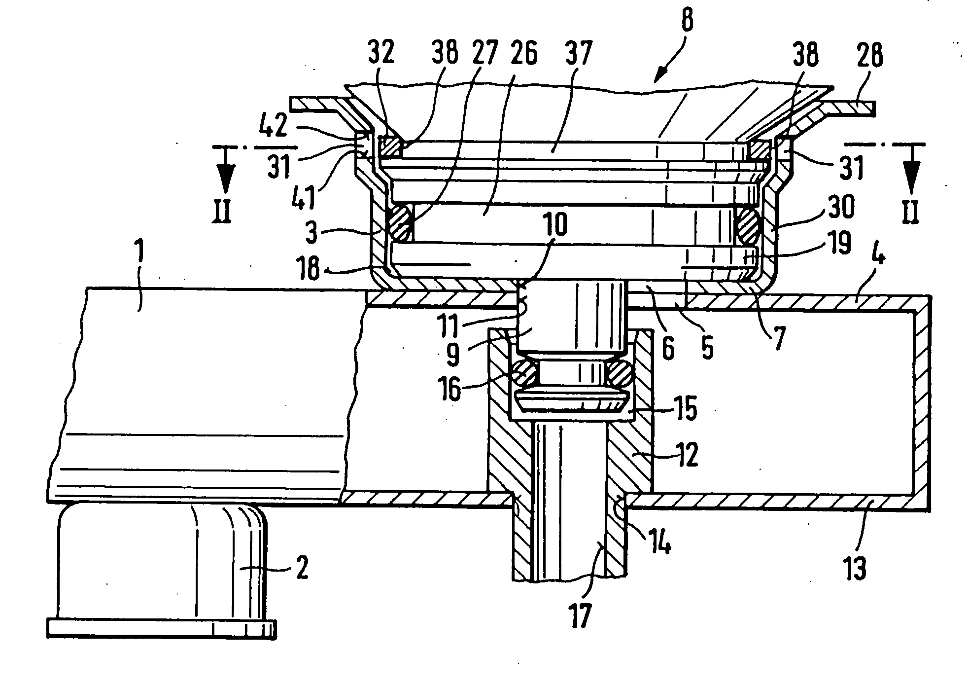
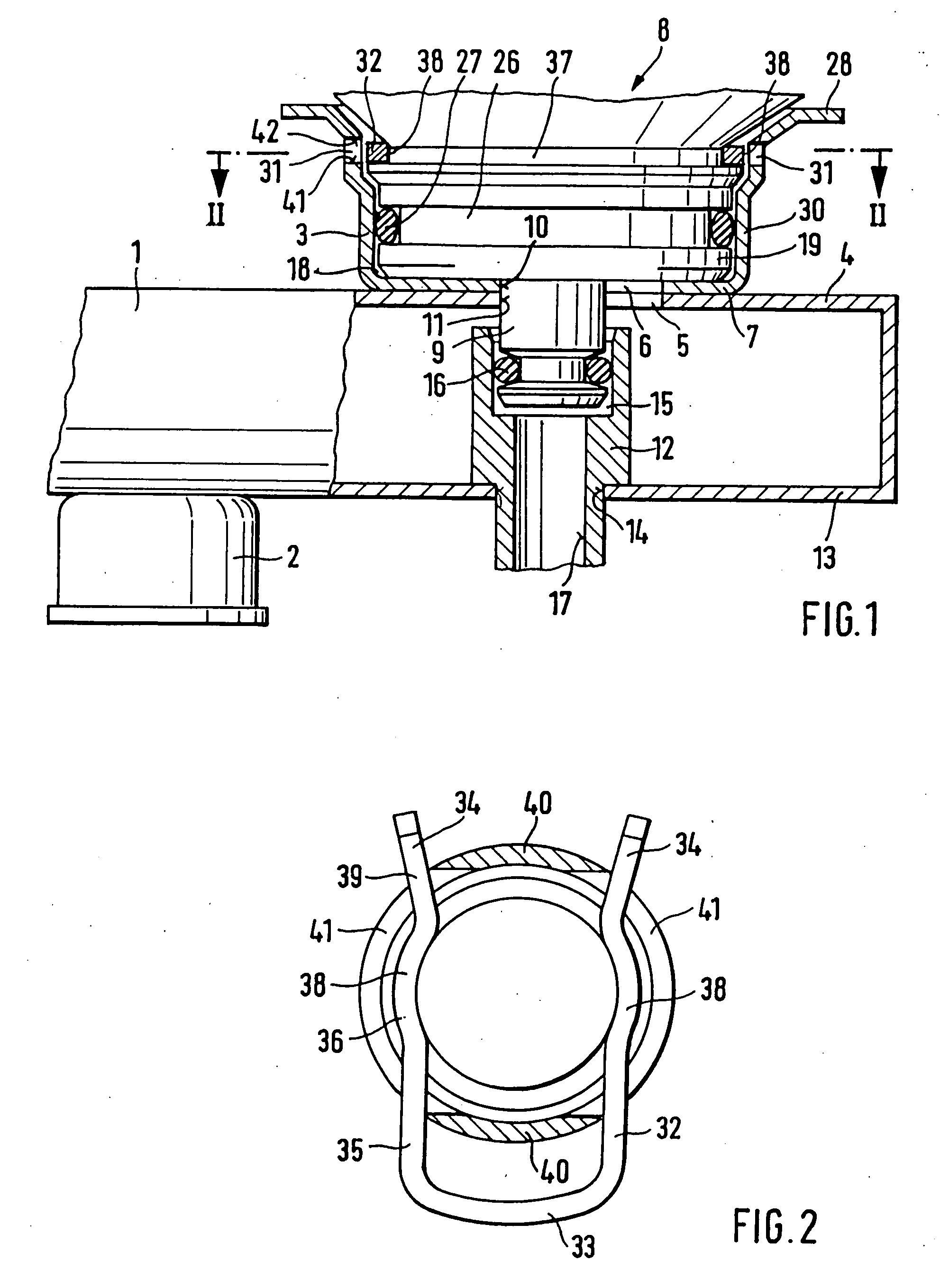
[0016] In the exemplary embodiment of FIG. 1 and FIG. 2, reference numeral 1 indicates a fuel distributor line in a fuel supply system for internal combustion engines; this line has a plurality of plug connectors 2, into which fuel injection valves are inserted by one end. A cup-shaped receiving bush 3 is connected, for instance by being soldered or welded, to the wall of the fuel distributor line 1. The receiving bush 3 can also be formed onto the fuel distributor line I and / or can project at least partway into the fuel distributor line 1. At least one inlet opening 5 is provided in the wall 4, toward the receiving bush 3, of the fuel distributor line 1, and this opening is aligned with a connecting opening 6 in the bottom 7 of the receiving bush 3. The inlet opening 5 and the connecting opening 6 can also have an annular shape. A pressure regulating valve 8 is inserted into a guide sleeve portion 18 of the receiving bush 3; with a valve seat carrier body 9, it projects through a f...


PUM


Abstract

The invention relates to a connection of two coaxially in-line elements in a fuel supply system of an internal combustion engine, in which the first element is preferably a receiving bush of a fuel distributor line with a guide opening, and the second element, embodied as a pressure regulating valve or pressure chamber, is insertable by a guide portion into the guide opening of the receiving bush, which facing one another in a wall has two retention openings, aligned both with one another and with a retention groove in the pressure regulating valve, which openings a U-shaped retention clamp projects through with its legs and in so doing fixes the position of the first element and second element relative to one another, which elements, at least in the region of the retention clamp have portions of stainless steel. Alternatively, the first element may be an injection valve, which is inserted by one end into a plug connection, forming the second element, of the fuel distributor line, where it is fixed by means of a securing clamp, and the injection valve and the plug connection, at least in the region of the securing clamp, have portions of stainless steel. The invention provides that the retention clamp is formed by a spring wire and the securing clamp is formed of a spring band of stainless steel, in order to prevent contact corrosion.

Description

CROSS-REFERENCE TO RELATED APPLICATIONS [0001] This application is a continuation of prior application Ser. No. 10 / 275,313, which was the National Stage of International Application No. PCT / DE 02 / 00892, filed on Mar. 13, 2002.BACKGROUND OF THE INVENTION [0002] 1. Field of the Invention [0003] The invention is based on a connection of two coaxially in-line elements in a fuel supply system of an internal combustion engine. [0004] 2. Description of the Prior Art [0005] From German Patent Disclosure DE 36 07 811 A1, a connection is known which is used for fixing a pressure regulating valve in a receiving bush that extends transversely to a fuel distributor line of a motor vehicle and which has a through bore that is in communication with an inlet opening of the fuel distributor line. To that end, a bottom part of the pressure regulating valve is inserted into the through bore of the receiving bush, which has two slots, facing one another in a wall and aligned both with one another and w...

Claims


Application Information

Patent Timeline
Patent Type & Authority Applications(United States)
IPC IPC(8): F02M69/54F02M55/00F02M61/16F02M69/46
CPCF02M55/004F02M61/168F02M69/465F02M2200/8023F02M2200/803F02M37/00
Inventor SCHOEFFLER, JOCHEN
Owner SCHOEFFLER JOCHEN
Learn More