Ventilation system for respiratory devices

a technology for respiratory devices and ventilation systems, which is applied in the direction of valve details, operating means/releasing devices, medical devices, etc., can solve the problems of compromising hemodynamics, increasing respiratory work, and leaking gas before the bellows is fully filled, so as to eliminate the risks of pressure trauma and effective control of excess

Inactive Publication Date: 2006-06-15
INTERMED EQUIPAMENTO MEDICO HOSPITALAR
View PDF10 Cites 42 Cited by
  • Summary
  • Abstract
  • Description
  • Claims
  • Application Information

AI Technical Summary

Benefits of technology

[0022] Another object of the present invention is to provide a ventilation system for respiratory circuits with re-inhalation that promotes an effective control of the excess of fresh gas, as well as the control of the internal pressure of the respiratory circuit. The present invention can also adequate the respiratory circuit to the spontaneous breathing of patients, not requiring efforts from the respiratory system, besides providing an appropriate and controlled respiratory cycle to patients.
[0023] It is also a further object of the invention to provide a valve for the free flow of oxygen that actuates synchronously with the exhaling stage of respiratory cycles, in order to eliminate the risks of pressure trauma without intervening in the lung ventilation of patients.

Problems solved by technology

Consequently, there is gas leakage before the bellows is fully filled in.
This is very undesirable because inhibits the use of low fresh gas flow and requires the reposition of flow above the clinically desired level.
Furthermore, the release systems of the state of the art present another inconvenience.
This makes the more difficult ventilator synchronism with the spontaneous breathing of the patient, consequently increasing the respiratory work and compromising hemodynamics, especially for cardiopathic patients.
However, this system is not appropriate for newly born and pediatric applications, since it promotes undesirable positive pressure during system operation.
This inconvenience is caused by the fact that there is no constant relationship between the volume of the flexible reservoir and the position of its flexible wall, as well as between the sensor's contact area and consequently the force exerted by the bag and the required force to activate the release system.
Another inconvenience disclosed by the devices of the state of the art relates to the valve for the free flow of oxygen, which purpose is to quickly replace or renew the gas inside the respiratory circuit.
However, in automatically configured respiratory circuits, said free flow of oxygen may cause excessive increase of volume and pressure sent to the patient and may cause serious damage to the respiratory system or even to patient's hemodynamic.
However, despite eliminating the risk of pressure trauma caused by the overlaying of the respiratory cycle and the activation of the free flow of oxygen, this alternative interferes with the lung ventilation of the patient and may cause a reduction of oxygenation (hypoxia) and / or increase of CO2 retention (hypercapnia), which may compromise the health of patients.
Therefore, it is verified that the ventilation systems of the state of the art have serious inconveniences to patients, especially because they do not meet the technical and medical requirements for the administration of anesthesia through respiratory circuits with re-inhalation, since they can generate inefficient and dangerous gas flow to patient's respiratory system.

Method used


Image

  • Ventilation system for respiratory devices
  • Ventilation system for respiratory devices
  • Ventilation system for respiratory devices

Examples


Embodiment Construction

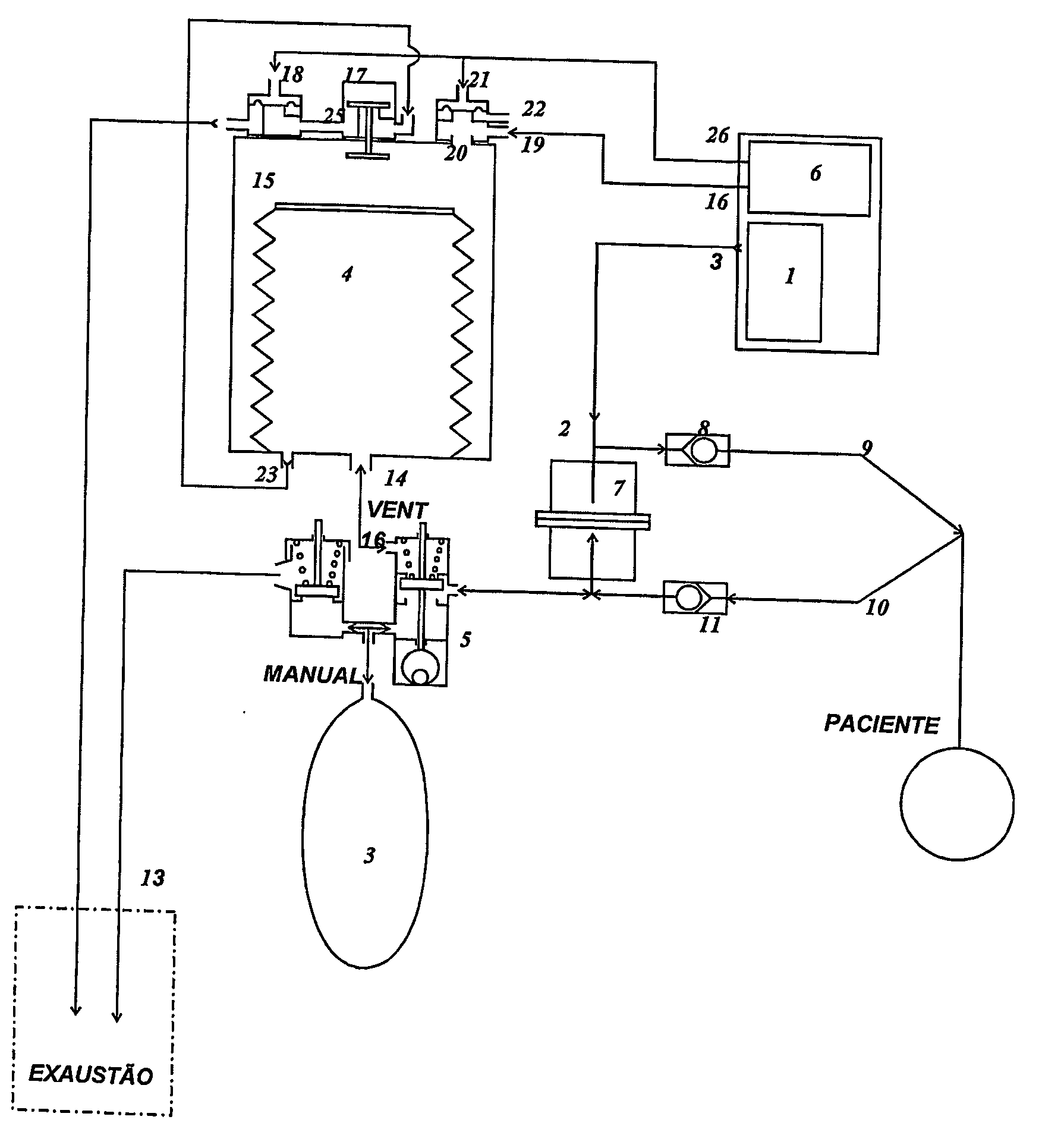
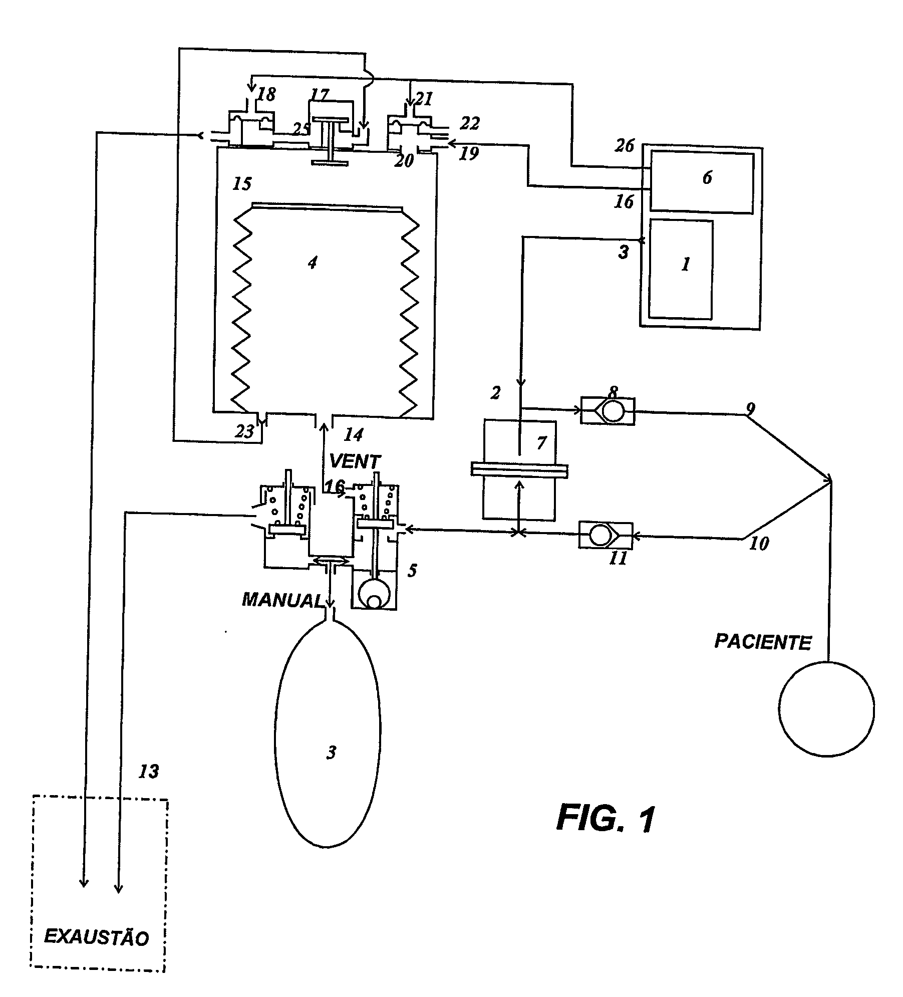
[0032] The FIG. 1, as mentioned above, shows a schematic diagram of the respiratory cycle with re-inhalation of a respiratory device provided with the ventilation system of the present invention. As illustrated in FIG. 1, the fresh gas coming from the anesthesia equipment (1), that adequately adjusts the composition of gases and the concentration of anesthetic agents, is introduced in the respiratory circuit through the fresh gas inlet (2). The gas is collected in a bag (3) or bellows (4), depending on the application requirements and according to the position of the selecting key (5), which determines the mode of operation of the device: manual or automatic through a lung ventilator (6).

[0033] In case the selecting key (5) is in the manual position, the bag (3) is filled in with gas, so that the anesthesia physician or any other specialist may manually pump the gas to patient. When the bag is pressed, the gas passes through a carbon dioxide absorber (7), through the inhaling unidi...


PUM


Abstract

The present invention refers to a ventilation system used in hospital respiratory devices for the administration of anesthesia to newly born, pediatric and adult patients. More specifically, the present invention refers to a ventilation system that promotes a respiratory circuit with re-inhalation for the administration of anesthesia and that overcomes all inconveniences and deficiencies existing in respiratory devices of the state of the art. The ventilation system in respiratory devices comprises a bellows assembled within a reservoir, which is provided with a manifold with various gas exhaling valves, more specifically release valves to take out the excess of gases, and an exhaling valve for control gases. It is additionally constituted of a valve for the free flow of oxygen to quickly renew or replace the gases inside the respiratory circuit.

Description

FIELD OF THE INVENTION [0001] The present invention refers to a ventilation system for hospital respiratory devices that are used to administer anesthesia in patients. [0002] More specifically, the invention refers to a ventilation system used in a respiratory circuit with re-inhalation by means of an upstream bellows that is activated by a microprocessed electronic ventilator and provided with a fresh gas control system. [0003] The present invention is appropriate for the use in respiratory devices to administer anesthesia in newly born, pediatric and adult patients. [0004] Additionally, the ventilation system of the present invention controls appropriately, efficiently and safely the excess of gas inside the respiratory circuit, thus eliminating the waste of fresh gas, promoting more efficient and safe breathing to patients, and not requiring harmful efforts for the respiratory cycle. BACKGROUND OF THE INVENTION [0005] The inhalatory administration of anesthesia is made by means o...

Claims


Application Information

Patent Timeline
Patent Type & Authority Applications(United States)
IPC IPC(8): A61M16/00A62B7/00
CPCA61M16/00A61M16/0075A61M16/0081A61M16/20A61M2240/00A61M16/0078A61M16/22A61M16/205A61M16/026A61M16/208A61M16/207A61M16/203A61M16/209
Inventor BONASSA, JORGE
Owner INTERMED EQUIPAMENTO MEDICO HOSPITALAR
Why Eureka
Try Eureka