Surface modification method

a surface modification and surface technology, applied in the field of surface modification methods, can solve the problems of poor and impractical surface modification throughput, and none can provide light energy or repetition frequency suitable for surface modification, and achieve the effect of higher throughput modification and effective control of discoloration

Inactive Publication Date: 2009-11-12
SUMITOMO ELECTRIC IND LTD +3
View PDF4 Cites 11 Cited by
  • Summary
  • Abstract
  • Description
  • Claims
  • Application Information

AI Technical Summary

Benefits of technology

[0013]In the surface modification method of the present invention, the pulse width of the pulsed-laser light output from the pulsed-laser device is preferably not more than 10 ns. This will allow discoloration to be even more effectively controlled.
[0014]In the surface modification method of the present invention, the repetition frequency of the pulsed-laser light output from the pulsed-laser device is preferably at least 50 kHz. This will enable higher throughput modification of the work piece surface.

Problems solved by technology

This has resulted in poor and impractical surface modification throughput.
In order to produce pulsed light, methods such as Q-switching and mode locking have been proposed for gas laser light sources and solid laser light sources, but none can provide light energy or repetition frequency suitable for surface modification.

Method used


Image

  • Surface modification method
  • Surface modification method
  • Surface modification method

Examples


Embodiment Construction

[0034]In the following, embodiments of surface modification method according to the present invention will be described in detail with reference to FIGS. 1, 2, 3A-3B, 4, 5A-5D, 6 to 9, 10A-13B, and 14-16. In the description of the drawings, identical or corresponding components are designated by the same reference numerals, and overlapping description is omitted.

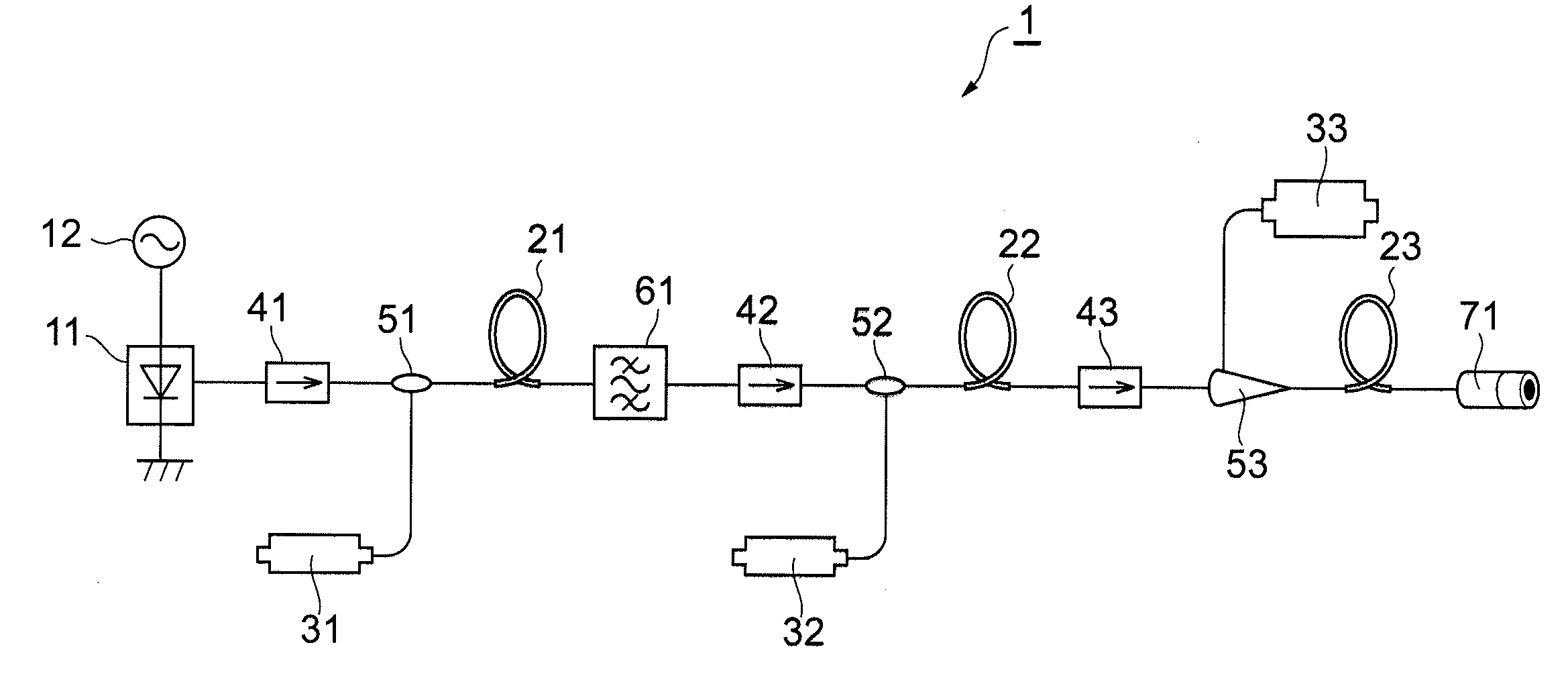
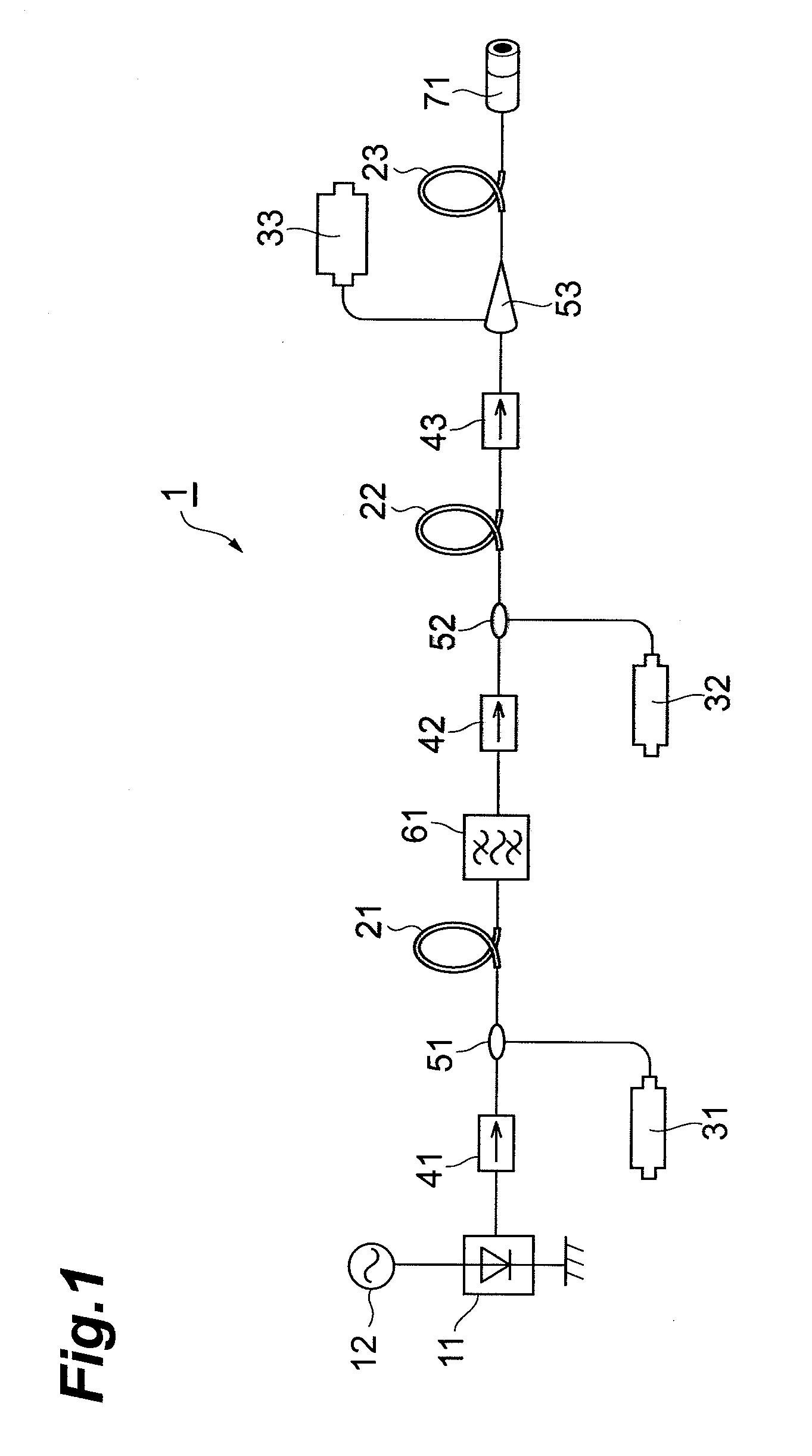
[0035]FIG. 1 is a structural diagram of a pulsed-laser device 1 suitable for use in the surface modification method of the invention. The pulsed-laser device 1 shown in the figure is equipped with a semiconductor laser light source 11, modulator 12, fibers 21 through 23 for optical amplification, excitation light sources 31 through 33, isolators 41 through 43, couplers 51 and 52, combiner 53, band pass filter 61, and collimator 71. The pulsed-laser device 1 allows the pulse width and repetition frequency of the output pulsed-laser light to be adjusted independently of each other. The pulse width of the pulsed-laser light out...


PUM

PropertyMeasurementUnit
repetition frequencyaaaaaaaaaa

Abstract

The present invention relates to a surface modification method allowing the surface of a subject to be more effectively modified. In a pulsed-laser device suitable for use in this surface modification method, a semiconductor laser light source and a modulator constitute a seed light source. The seed light output from the seed light source is amplified by fibers for optical amplification, and the amplified light constitutes output from the pulsed-laser device. The pulsed-laser device allows the pulse width and repetition frequency of the output pulsed-laser light to be varied independently of each other. The pulse width of the pulsed-laser light output from the pulsed-laser device is preferably not more than 10 ns, and the repetition frequency is preferably at least 50 kHz.

Description

BACKGROUND OF THE INVENTION[0001]1. Field of the Invention[0002]The present invention relates to a method of modifying the surface of a work piece by irradiating the work piece with laser light.[0003]2. Related Background Art[0004]Techniques for modifying the surface of a work piece by irradiating the work piece with laser light are well known. In the surface modification method described in Japanese Patent Application Laid-Open No. 2006-231353 (Document 1), for example, the surface of a work piece is modified by irradiating the work piece with an ultrashort pulsed-laser beam and scanning the locations that are irradiated. Surface modification also includes the modification of properties such as hydrophilicity, water repellency, electromagnetic waves, sound waves, and electrical charge.[0005]In the surface modification described in Document 1 above, the work piece is irradiated with an ultrashort pulsed-laser beam, specifically, an ultrashort pulsed-laser beam with a pulse width in ...

Claims


Application Information

Patent Timeline
Patent Type & Authority Applications(United States)
IPC IPC(8): B23K26/00B23K26/12B23K26/14B23K26/352H01S5/00
CPCB23K26/0072B23K26/063B23K26/127B23K26/12B23K2201/20B23K26/0807B23K26/082B23K26/0622B23K26/3568B23K2101/20
Inventor UNO, YOSHIYUKIOKAMOTO, YASUHIROMOHRI, TETSUOMITANAKA, YUJIKAKUI, MOTOKINAKAMAE, KAZUO
Owner SUMITOMO ELECTRIC IND LTD
Why Eureka
Try Eureka