Apparatus for controlling driving force of vehicle

Inactive Publication Date: 2006-06-15
GKN DRIVELINE TORQUE TECHNOLOGY KK
View PDF2 Cites 26 Cited by
  • Summary
  • Abstract
  • Description
  • Claims
  • Application Information

AI Technical Summary

Benefits of technology

[0011] If one of the drive wheels spins without traction to cause differential rotation between the drive wheels, the brake controller conducts to brake the spinning drive wheel. As a result, torque which is transmitted to the other drive wheel that is not spinning is increased, accordin

Problems solved by technology

Namely, the drive wheel that is not s

Method used


Image

  • Apparatus for controlling driving force of vehicle
  • Apparatus for controlling driving force of vehicle
  • Apparatus for controlling driving force of vehicle

Examples


first embodiment

[0027] [Four-Wheel-Drive Vehicle]

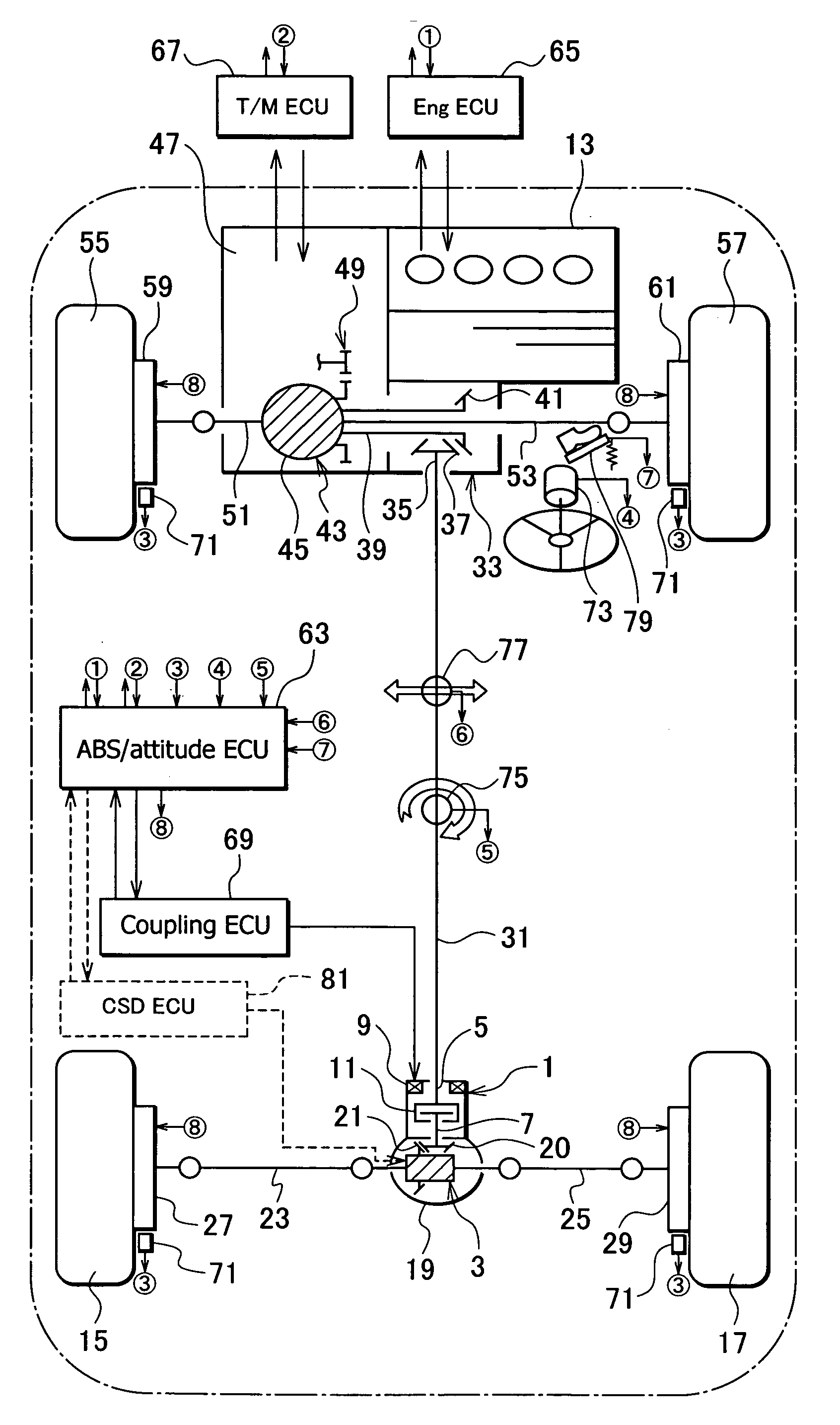
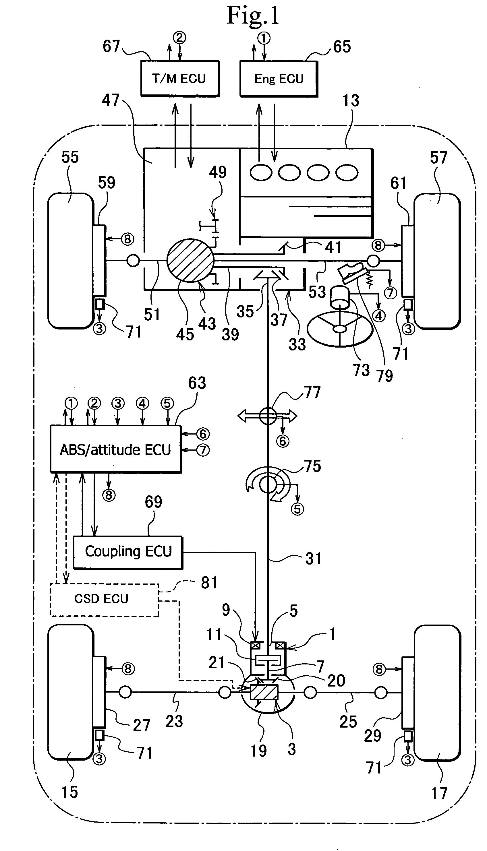
[0028]FIG. 1 is a plan view generally showing a four-wheel-drive vehicle having a driving force control apparatus according to the first embodiment of the present invention. This vehicle is a front-engine, front-drive vehicle, i.e., an FF vehicle.

[0029] In FIG. 1, a torque transmission coupling 1 serving as a torque connection / disconnection mechanism is arranged on the input side of a rear differential 3. The torque transmission coupling 1 is placed between a rotary shaft 5 and a drive pinion shaft 7, to operate the vehicle as an on-demand-type four-wheel-drive vehicle.

[0030] The torque transmission coupling 1 is of an active type and has an electromagnet 9 serving as an actuator. With magnetic force of the electromagnet 9, the torque transmission coupling 1 controls engaging force on a multiplate clutch 11, to thereby control torque transmission from the rotary shaft 5 to the drive pinion shaft 7. The multiplate clutch 11 includes, for example, a ...

second embodiment

[0100]FIG. 15 is a plan view generally showing a four-wheel-drive vehicle having a driving force control apparatus according to a second embodiment of the present invention. In FIG. 15, the same or corresponding parts as those of FIG. 1 are represented with the same reference numerals or the same reference numerals plus “A.”

[0101] The four-wheel-drive vehicle of FIG. 15 is a longitudinal front-engine, rear-drive (FR) vehicle. According to the second embodiment, a front wheel side serves as a secondary drive side, and therefore, a torque transmission coupling 1A is provided for a front differential 43A. The torque transmission coupling 1A is engaged with a drive pinion shaft 83 having a drive pinion gear 85. The drive pinion gear 85 meshes with a ring gear 87 of the front differential 43A, to form a final reduction mechanism. The front differential 43A on the secondary drive side and a rear differential 3 on a primary drive side each have a passive-type differential limiting mechanis...

third embodiment

[0113]FIG. 16 is a plan view generally showing a four-wheel-drive vehicle having a driving force control apparatus according to a third embodiment of the present invention. In FIG. 16, the same or corresponding parts as those of FIG. 1 are represented with the same reference numerals or the same reference numerals plus “B.”

[0114] The four-wheel-drive vehicle of FIG. 16 is a lateral front-engine, front-drive (FF) vehicle. The driving of the rear wheels is electrically assisted. A primary drive side is a front wheel side and a secondary drive side is a rear wheel side.

[0115] On the primary drive side (first drive side), torque of an engine (first drive source) 13 is transmitted through a main clutch 103 and a CVT (continuously variable transmission) 105 to a front differential 43.

[0116] On the secondary drive side (second drive side), torque of an electric motor (second drive source) 107 is transmitted through a reduction gear 109 and a torque connect / disconnect unit 111 to a rear d...


PUM


Abstract

An apparatus for controlling the driving force of a vehicle is capable of using brakes to limit a differential operation, securing sufficient torque, and suppressing the heating and wearing of the brakes. In the vehicle, an engine generates torque to drive front wheels and/or rear wheels. A front differential allows differential rotation between the front wheels and transmits torque of the engine to the front wheels. A rear differential allows differential rotation between the rear wheels and transmits torque of the engine to the rear wheels. Disk brakes separately brake the front and rear wheels. An ABS/attitude electric control unit controls the disk brakes to limit differential rotation between the front wheels or between the rear wheels. At least one of the front and rear differentials is provided with a differential limiting mechanism.

Description

BACKGROUND OF THE INVENTION [0001] 1. Field of the Invention [0002] The present invention relates to an apparatus for controlling the driving force of a vehicle. [0003] 2. Description of Related Art [0004] A vehicle generally employs a differential mechanism to transfer driving force from an engine to left and right drive wheels and smoothly turn a corner. In the case of a four-wheel-drive vehicle, a center differential mechanism is frequently employed. If one of the drive wheels spins without traction, the differential mechanism transmits torque from the engine to the spinning drive wheel. If this happens, the vehicle will be unable to escape from this state. [0005] To prevent this, the differential mechanism is usually provided with a differential limiting mechanism. If one of the drive wheels loses traction, the differential limiting mechanism limits differential rotation of the differential mechanism, to help the vehicle smoothly escape from such a state. [0006] Japanese Unexami...

Claims


Application Information

Patent Timeline
IPC IPC(8): B60K17/34
CPCB60K6/52B60K23/04B60K23/08B60K23/0808B60K28/165B60T8/175B60T8/3205B60T8/3215B60T8/322B60T2201/14B60W10/08B60W10/119B60W10/16B60W10/18B60W10/184B60W20/00B60W30/18B60W2520/26Y02T10/6265Y02T10/62B60W20/15
Inventor KATADA, KUNIONOGUCHI, MASATOSHITERAOKA, MASAO
Owner GKN DRIVELINE TORQUE TECHNOLOGY KK
Why Eureka
Try Eureka