Pressure foot clamping apparatus and methods

a technology of pressure foot and clamping device, which is applied in the direction of soldering apparatus, manufacturing tools,auxillary welding devices, etc., can solve the problems of uncontrolled filling between workpieces, and achieve the effect of preventing filling within the workpi

Active Publication Date: 2006-06-15
THE BOEING CO
View PDF79 Cites 48 Cited by
  • Summary
  • Abstract
  • Description
  • Claims
  • Application Information

AI Technical Summary

Benefits of technology

[0004] The present invention is directed to apparatus and methods for clamping and controlling flash around a manufacturing tool engaging a workpiece and preventing fill within the workpiece. In one embodiment, a clamp for securing a workpiece during a manufacturing operation includes a housing, and a foot biased away from the housing, the foot defining an opening through which a manufacturing tool may pass to engage the workpiece. In another embodiment, the manufacturing tool is a rotating or counter-rotating shoulder friction stir spot welding tool. In accordance with other aspects of the invention, the foot defines at least one recess for holding flashing.

Problems solved by technology

In friction stir welding, plunging the friction stir welding tool into a workpiece can push the parts of the workpiece being welded away from each other, and can result in uncontrolled fill between the work pieces due to sheet lifting, and / or flash up into the welding tool.

Method used


Image

  • Pressure foot clamping apparatus and methods
  • Pressure foot clamping apparatus and methods
  • Pressure foot clamping apparatus and methods

Examples


Embodiment Construction

[0015] The present invention relates to apparatus and methods for clamping and controlling flash around a manufacturing tool engaging a workpiece. Many specific details of certain embodiments of the invention are set forth in the following description and in FIGS. 1-6 to provide a thorough understanding of such embodiments. One skilled in the art, however, will understand that the present invention may have additional embodiments, or that the present invention may be practiced without several of the details described in the following description.

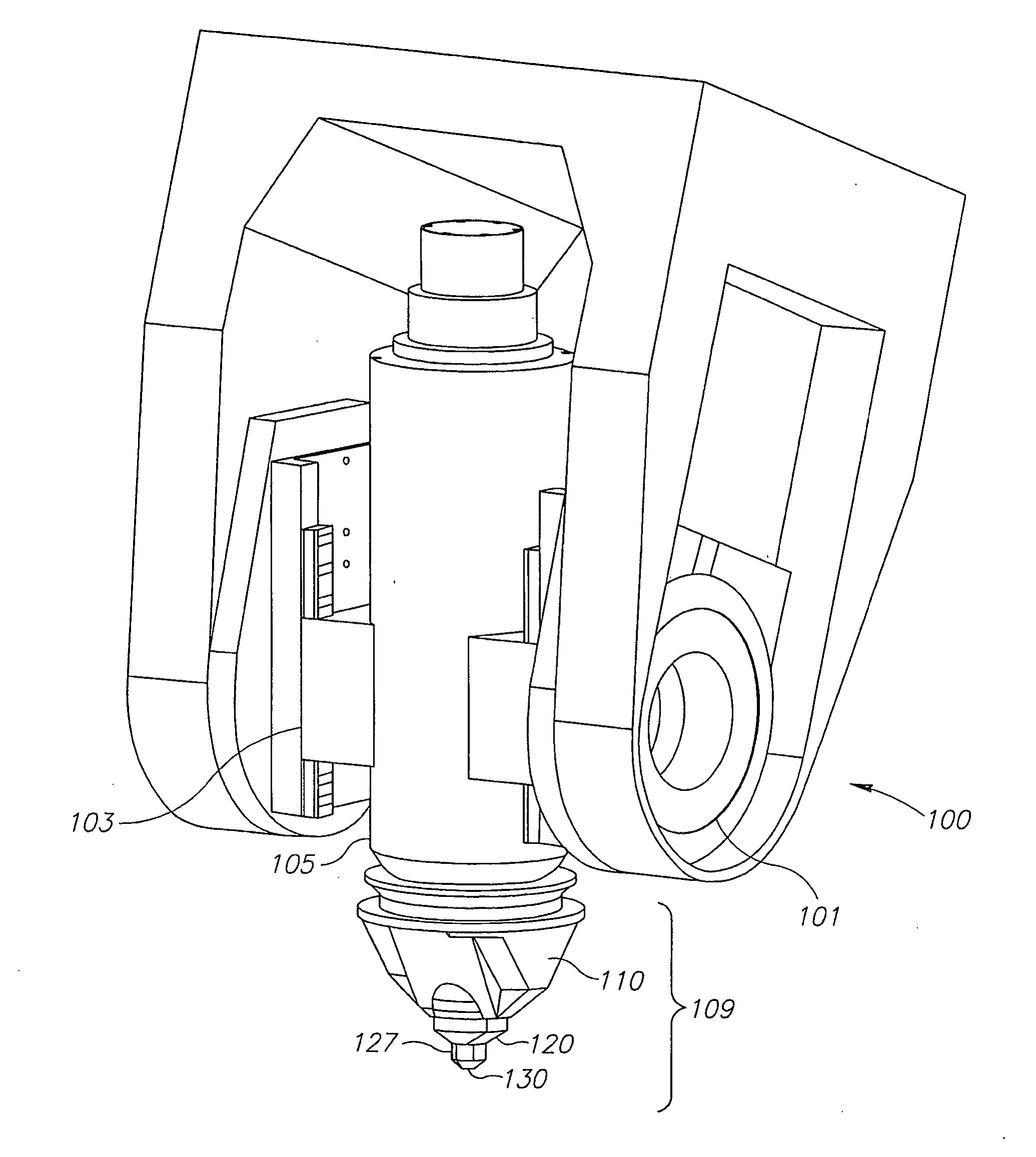
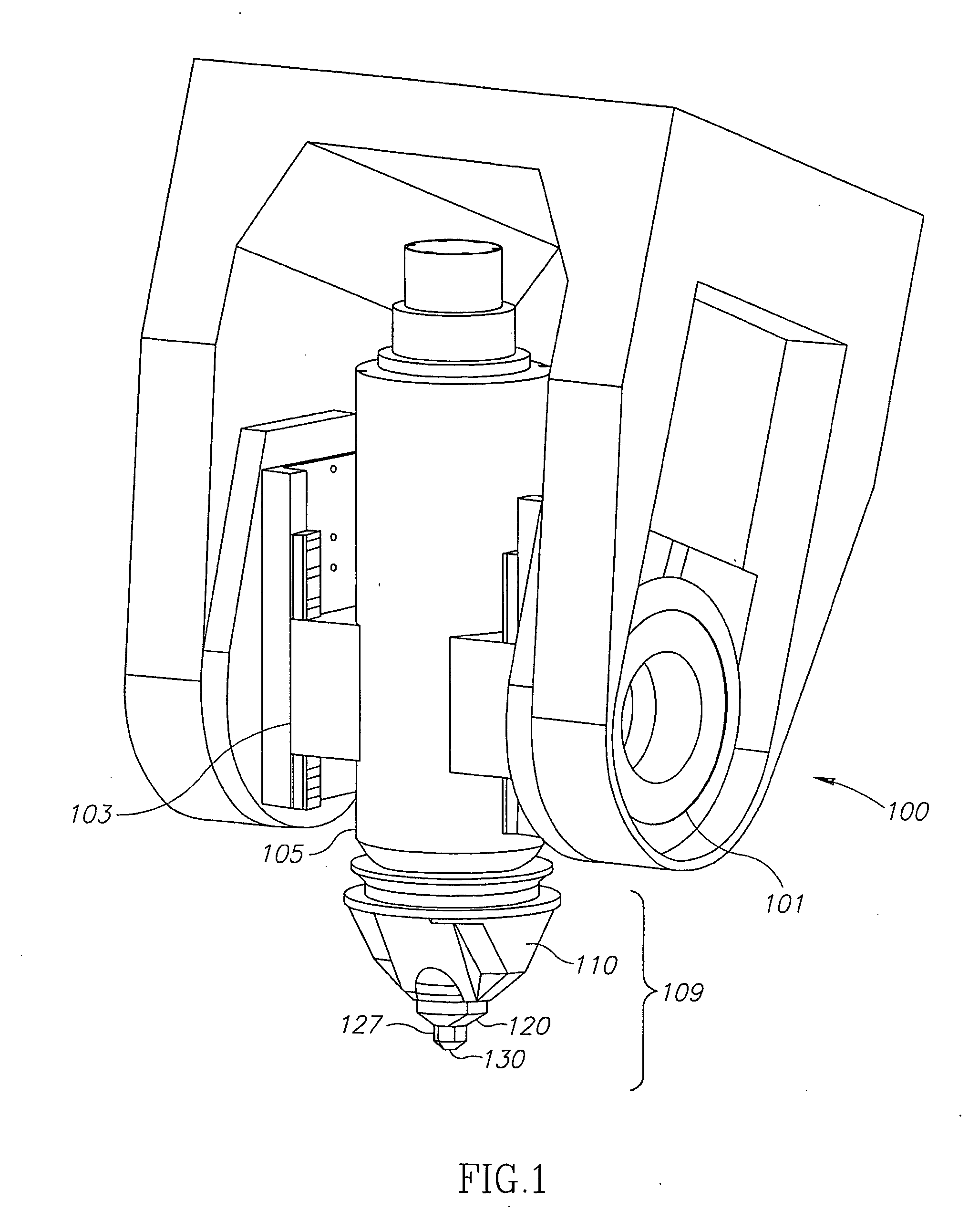
[0016]FIG. 1 is an isometric view of an exemplary friction stir spot welding head 100 in accordance with an embodiment of the present invention. The head 100 is the working portion of a friction stir spot welding machine. In this embodiment, the head 100 includes a dual spindle drive 105 configured to separately drive, advance, and retract a friction stir spot welding tool (not shown) and a shoulder tool (not shown), as described more fully...


PUM

PropertyMeasurementUnit
diameteraaaaaaaaaa
clamping forceaaaaaaaaaa
pressureaaaaaaaaaa

Abstract

The present invention is directed to apparatus and methods for clamping and controlling flash around a manufacturing tool engaging a workpiece and preventing fill within he workpiece. In one embodiment, a clamp for securing a workpiece during a manufacturing operation includes a housing and a foot biased away from the housing, the foot defining an opening through which a manufacturing tool may pass to engage the workpiece. In another embodiment, the manufacturing tool is a rotating or counter-rotating shoulder friction stir spot welding tool. In accordance with other aspects of the invention, the foot defines at least one recess for holding flashing.

Description

FIELD OF THE INVENTION [0001] This invention relates generally to assembly tools and, more specifically, to clamping mechanisms. BACKGROUND OF THE INVENTION [0002] The manufacture of certain types of equipment and vehicles, including aircraft, often involves the process of holding together sheets or sections of metal for attachment. Attachment of the sheets or sections of metal may include welding, including friction stir welding, or other bonding processes. [0003] In friction stir welding, plunging the friction stir welding tool into a workpiece can push the parts of the workpiece being welded away from each other, and can result in uncontrolled fill between the work pieces due to sheet lifting, and / or flash up into the welding tool. Accordingly, there is an unmet need in the art for clamping systems that can engage a workpiece close to a manufacturing tool, prevent sheet-lifting fill, and / or control flashing generated during manufacturing. SUMMARY [0004] The present invention is d...

Claims


Application Information

Patent Timeline
Patent Type & Authority Applications(United States)
IPC IPC(8): B23K20/12B23B35/00
CPCB23K20/1245B23K20/126Y10T428/12493B23K26/0661B23K20/1265
Inventor WOOD, JEFFREY H.MATLACK, MIKE P.
Owner THE BOEING CO
Why Eureka
Try Eureka