
Heart wall actuation device for the natural heart

Inactive Publication Date: 2008-04-22
UNIVERSITY OF CINCINNATI
View PDF103 Cites 19 Cited by
  • Summary
  • Abstract
  • Description
  • Claims
  • Application Information

AI Technical Summary

Benefits of technology

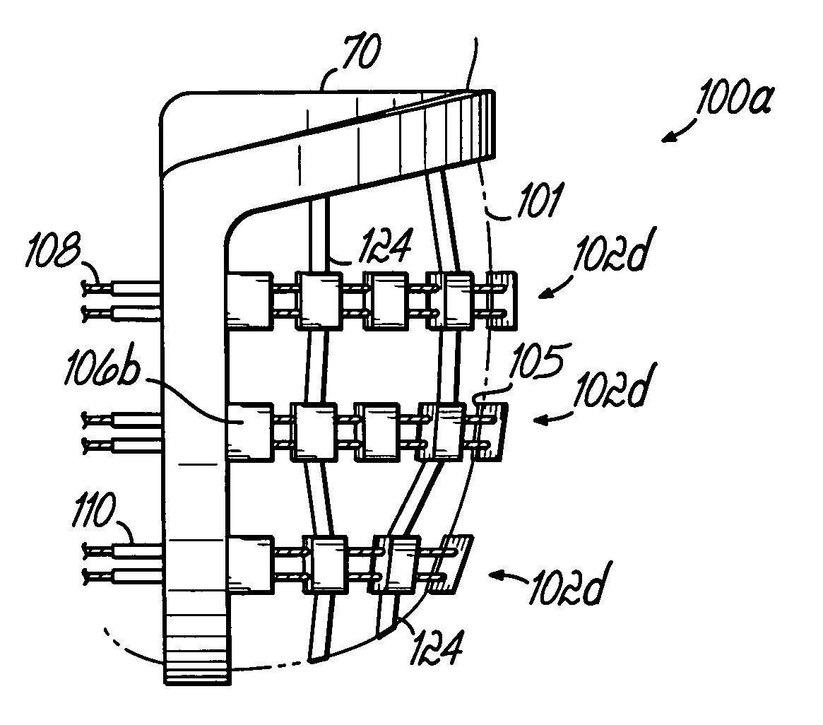
[0022]An actuator system is coupled to the framework and is configured to engage an exterior surface of the heart. For example, if the left ventricle of the heart is to be actuated utilizing the invention, the external framework element will be positioned proximate to the left ventricle exterior wall, and then the actuator system will be similarly positioned. The actuator system comprises an actuator band extending along a portion of the heart wall exterior surface. The actuator band is selectively movable between an actuated state and a relaxed state, and is operable, when in the actuated state, to assume a predetermined shape or curvature, and thereby indent a portion of the heart wall to effect a reduction in the volume of the heart, and specifically a reduction in one of the chambers of the heart, for assisting the heart in its pumping function.
[0023]In one embodiment of the invention, the actuator band includes a plurality of juxtaposed elements, such as blocks, which are coupled together by one or more actuator cords. The blocks are configured to be drawn together when the actuator band is in the actuated state, and to cooperate, with each other, when drawn together, to assume the predetermined shape or curvature. The one or more cords which couple the blocks together are coupled to a drive apparatus to be moved by that apparatus and draw the blocks together to achieve such predetermined shape. The blocks have adjacent cooperating surfaces which are at least partially coextensive with each other when the blocks are drawn together in the actuated state. The actuator band is coupled or fixed at one or both of its ends to the external framework element and the drive apparatus is operable for selectively moving the actuator band between the relaxed and actuated states to achieve the desired assistance of the natural heart. In accordance with another aspect of the present invention, one or more curvature limiting devices, such as curvature limiting bands, are coupled to the actuator band. The curvature limiting bands limit the predetermined shape or curvature that may be imposed by the actuator band, on the heart surface—at the actuator band edges, at the yoke edges, or elsewhere, when it is in the actuated state in order to reduce the severity of the indentation against the actuated portion of the heart wall. In that way, the heart wall is shaped, and the volume of the heart is changed in a less severe manner which will limit the stress on the heart wall and heart. Preferably, the curvature limiting bands are operable for limiting the curvature imposed on any part of the external heart wall to a certain measurable degree of the natural relaxed and distended curvature of the heart wall, along which the actuator band extends. When the actuator band is in the relaxed state, it is operable to generally assume the natural curve of the distended, relaxed heart wall and does not offer resistance to the refilling of the heart, such that active filling of the heart chambers may be avoided.
[0024]In another aspect of the present invention, a paving surface might be positioned between the epicardium, or exterior surface of the heart, and the actuator band in order to provide smoother actuation and less damage to the epicardium.

Problems solved by technology

A physical ailment or condition which compromises the normal and healthy operation of the heart can therefore be particularly critical and may result in a condition which must be medically remedied.
Specifically, the natural heart, or rather the cardiac tissue of the heart, can fail for various reasons to a point where the heart can no longer provide sufficient circulation of blood for the body so that life can be maintained.
In using artificial hearts and / or assist devices, a particular problem stems from the fact that the materials used for the interior lining of the chambers of an artificial heart are in direct contact with the circulating blood.
Such contact may enhance undesirable clotting of the blood, may cause a build-up of calcium, or may otherwise inhibit the blood's normal function.
As a result, thromboembolism and hemolysis may occur.
Additionally, the lining of an artificial heart or a ventricular assist device can crack, which inhibits performance, even when the crack is at a microscopic level.
Moreover, these devices must be powered by a power source which may be cumbersome and / or external to the body.
Such drawbacks have limited use of artificial heart devices to applications having too brief of a time period to provide a real lasting benefit to the patient.
Before replacing an existing organ with another, the substitute organ must be “matched” to the recipient, which can be, at best, difficult, time consuming, and expensive to accomplish.
Furthermore, even if the transplanted organ matches the recipient, a risk exists that the recipient's body will still reject the transplanted organ and attack it as a foreign object.
As currently used, skeletal muscle cannot alone typically provide sufficient and sustained pumping power for maintaining circulation of blood through the circulatory system of the body.
Typically, bypass systems of this type are complex and large, and, as such, are limited to short term use, such as in an operating room during surgery, or when maintaining the circulation of a patient while awaiting receipt of a transplant heart.
The size and complexity effectively prohibit use of bypass systems as a long term solution, as they are rarely portable devices.
Furthermore, long term use of a heart-lung machine can damage the blood cells and blood borne products, resulting in post surgical complications such as bleeding, thromboembolism function, and increased risk of infection.
Although somewhat effective as a short term treatment, the pumping device has not been suitable for long term use.
This “active filling” of the chambers with blood limits the ability of the pumping device to respond to the need for adjustments in the blood volume pumped through the natural heart, and can adversely affect the circulation of blood to the coronary arteries.
Furthermore, natural heart valves between the chambers of the heart and leaching into and out of the heart are quite sensitive to wall and annular distortion.
The movement patterns that reduce a chamber's volume and distort the heart walls may not necessarily facilitate valve closure (which can lead to valve leakage).
Another major obstacle with long term use of such pumping devices is the deleterious effect of forceful contact of different parts of the living internal heart surface (endocardium), one against another, due to lack of precise control of wall actuation.
However, it can compromise the integrity of the living endothelium.

Method used


Image

  • Heart wall actuation device for the natural heart
  • Heart wall actuation device for the natural heart
  • Heart wall actuation device for the natural heart

Examples


Embodiment Construction

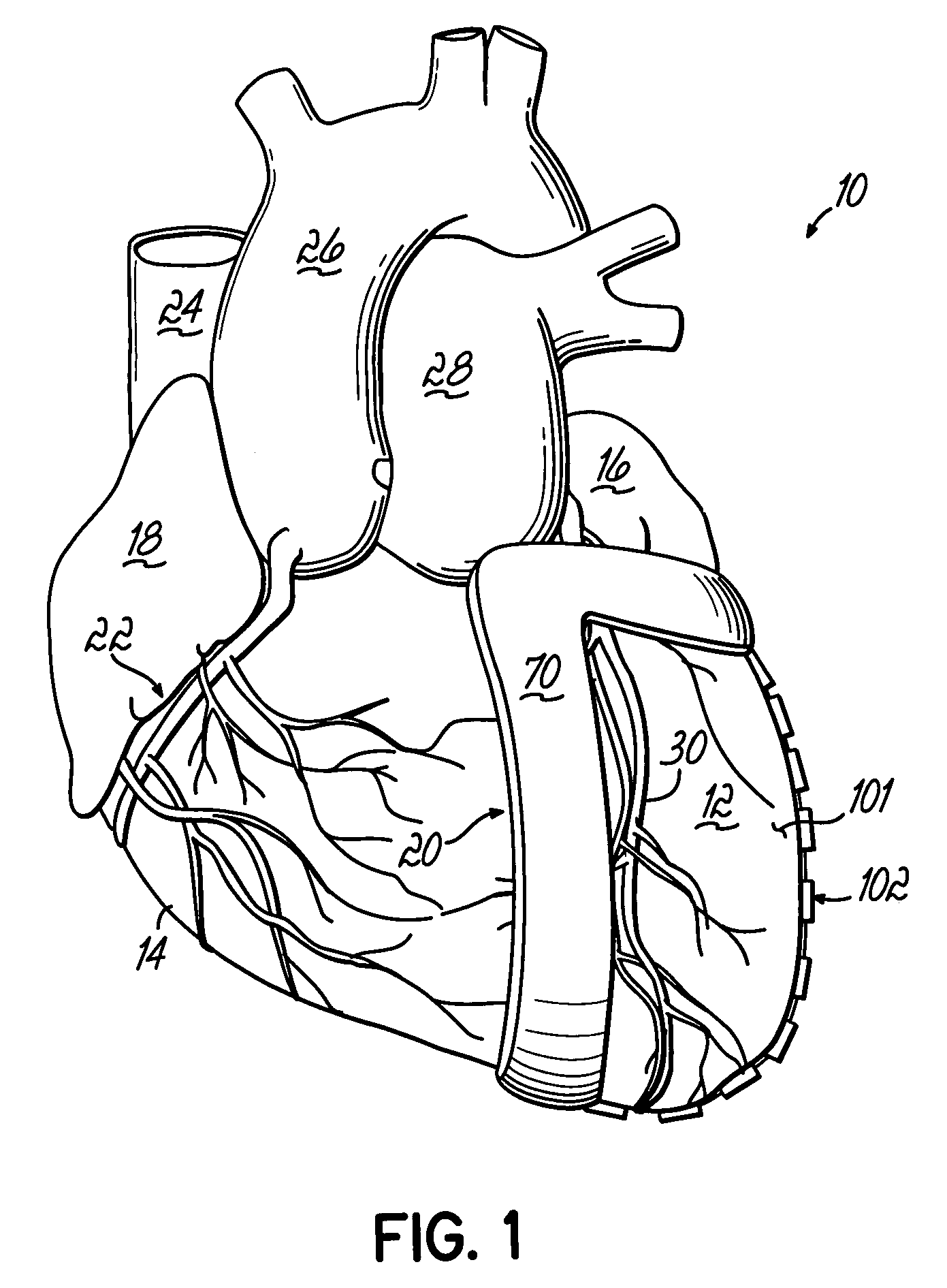
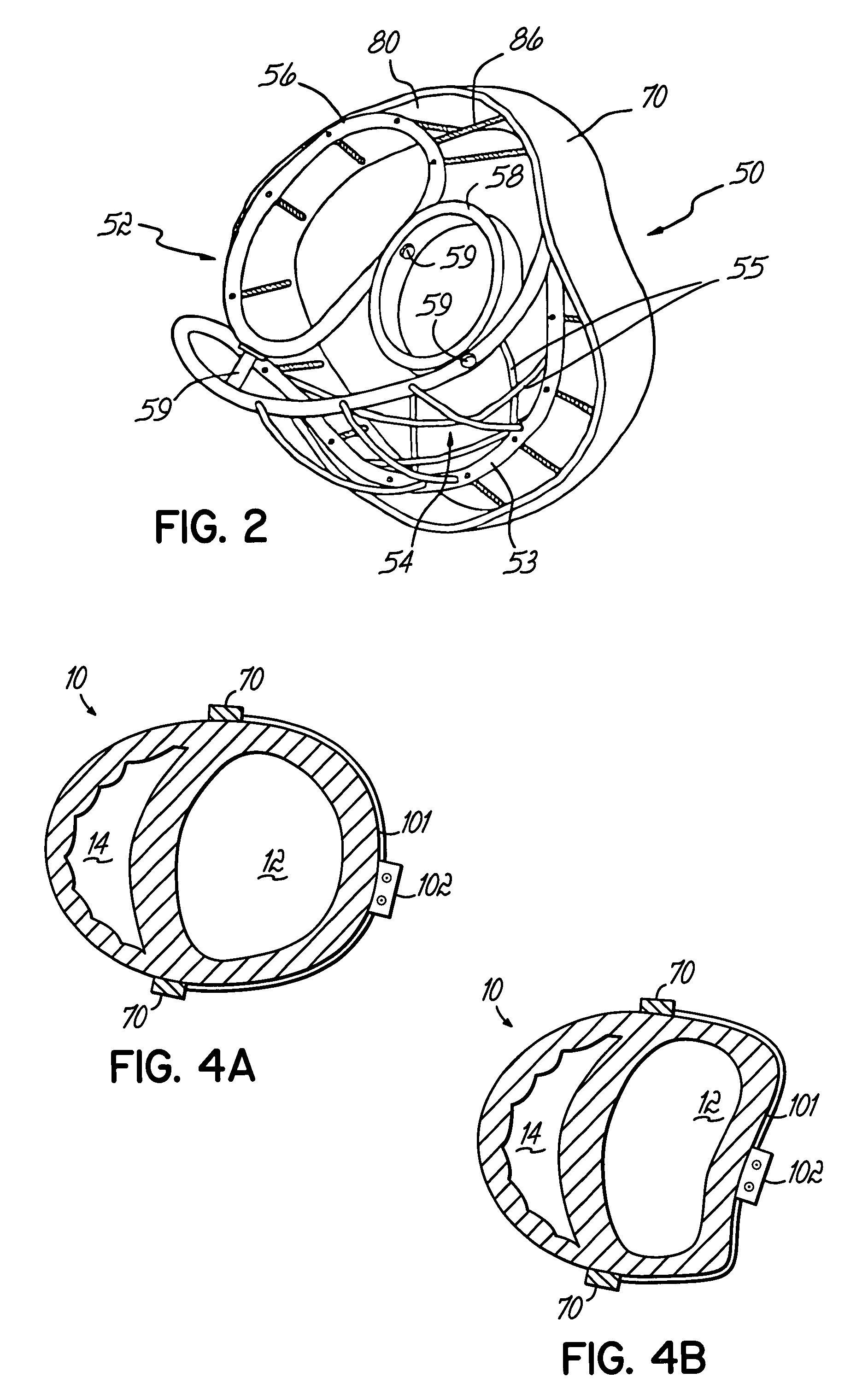
[0040]The present invention may best be described in the context of the natural human heart, and accordingly, the heart structure is discussed briefly below. Furthermore, the actuator system of the invention, in one embodiment, is coupled to a framework which cooperates with the human heart. One suitable framework for practicing the invention is disclosed in U.S. Pat. No. 5,957,977, to which priority is claimed, and which is incorporated herein by reference. Other frameworks may also be suitable. A brief overview of the framework of U.S. Pat. No. 5,957,977 is also set forth herein.

[0041]Referring now to FIG. 1, a natural human heart 10 is shown in perspective with a portion of the framework of the actuation system, and has a lower portion comprising two chambers, namely a left ventricle 12 and a right ventricle 14, which function primarily to supply the main pumping forces that propel blood through the circulatory system, including the pulmonary system (lungs) and the rest of the bo...


PUM


Abstract

An actuation system for assisting the operation of the natural heart comprises a framework for interfacing with a natural heart, through the wall of the heart, which includes an internal framework element configured to be positioned within the interior volume of a heart and an external framework element configured to be positioned proximate an exterior surface of the heart. The internal framework is flexibly suspended with respect to the external frame. An actuator system is coupled to the framework and configured to engage an exterior surface of the heart. The actuator system comprises an actuator band extending along a portion of a heart wall exterior surface. The actuator band is selectively movable between an actuated state and a relaxed state and is operable, when in the actuated state, to assume a predetermined shape and thereby indent a portion of the heart wall to effect a reduction in the volume of the heart. A drive apparatus is coupled to the actuator band and is operable for selectively moving the actuator band between the relaxed and actuated states to achieve the desired assistance of the natural heart.

Description

RELATED APPLICATIONS[0001]This application is a continuation application of U.S. patent application Ser. No. 09 / 850,554, filed May 7, 2001 (incorporated herein by reference), entitled “Heart Wall Actuation Device for the Natural Heart,” now U.S. Pat. No. 6,592,619, which is a continuation-in-part application of U.S. patent application Ser. No. 09 / 326,416, filed Jun. 4, 1999 (incorporated herein by reference), entitled “Device and Method for Restructuring Heart Chamber Geometry,” now U.S. Pat. No. 6,520,904, which is a continuation-in-part application of U.S. patent application Ser. No. 09 / 316,611, filed May 21, 1999 (incorporated herein by reference), entitled “Device and Method for Restructuring Heart Chamber Geometry,” now abandoned, which is a continuation-in-part U.S. patent application Ser. No. 09 / 165,887, filed Sep. 30, 1998 (incorporated herein by reference), entitled “Device and Method for Restructuring Heart Chamber Geometry,” now U.S. Pat. No. 6,221,103, which is a continu...

Claims


Application Information

Patent Timeline
IPC IPC(8): A61M1/10A61F2/00A61F2/02A61M60/191A61M60/289A61M60/465
CPCA61F2/02A61F2/2481A61M1/1068A61M1/122A61M1/106A61M60/148A61M60/289A61M60/191A61M60/465
Inventor MELVIN, DAVID BOYD
Owner UNIVERSITY OF CINCINNATI
Learn More