

Motor
- Summary
- Abstract
- Description
- Claims
- Application Information
AI Technical Summary
Benefits of technology
Problems solved by technology
Method used
Image

Examples
first embodiment
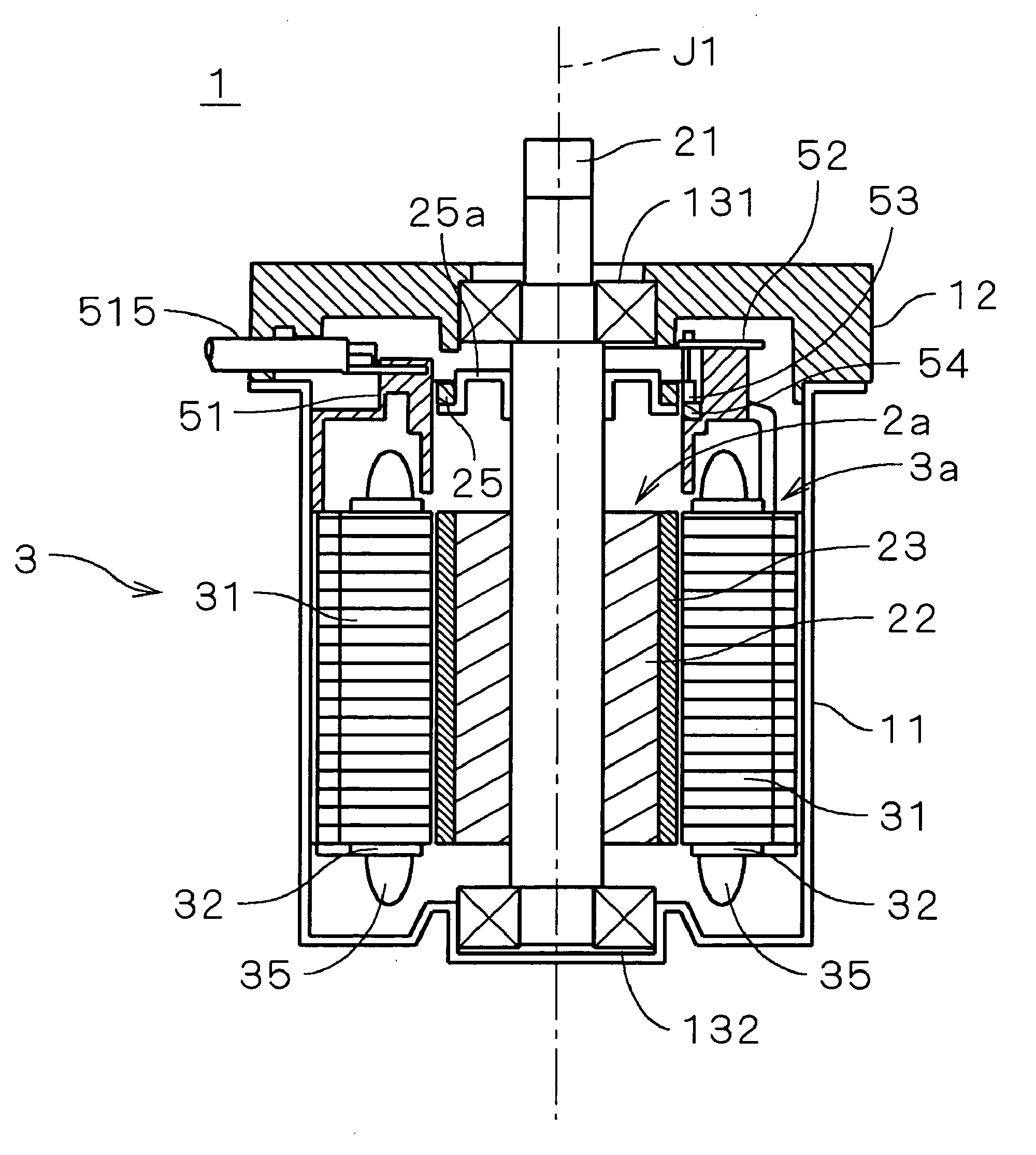
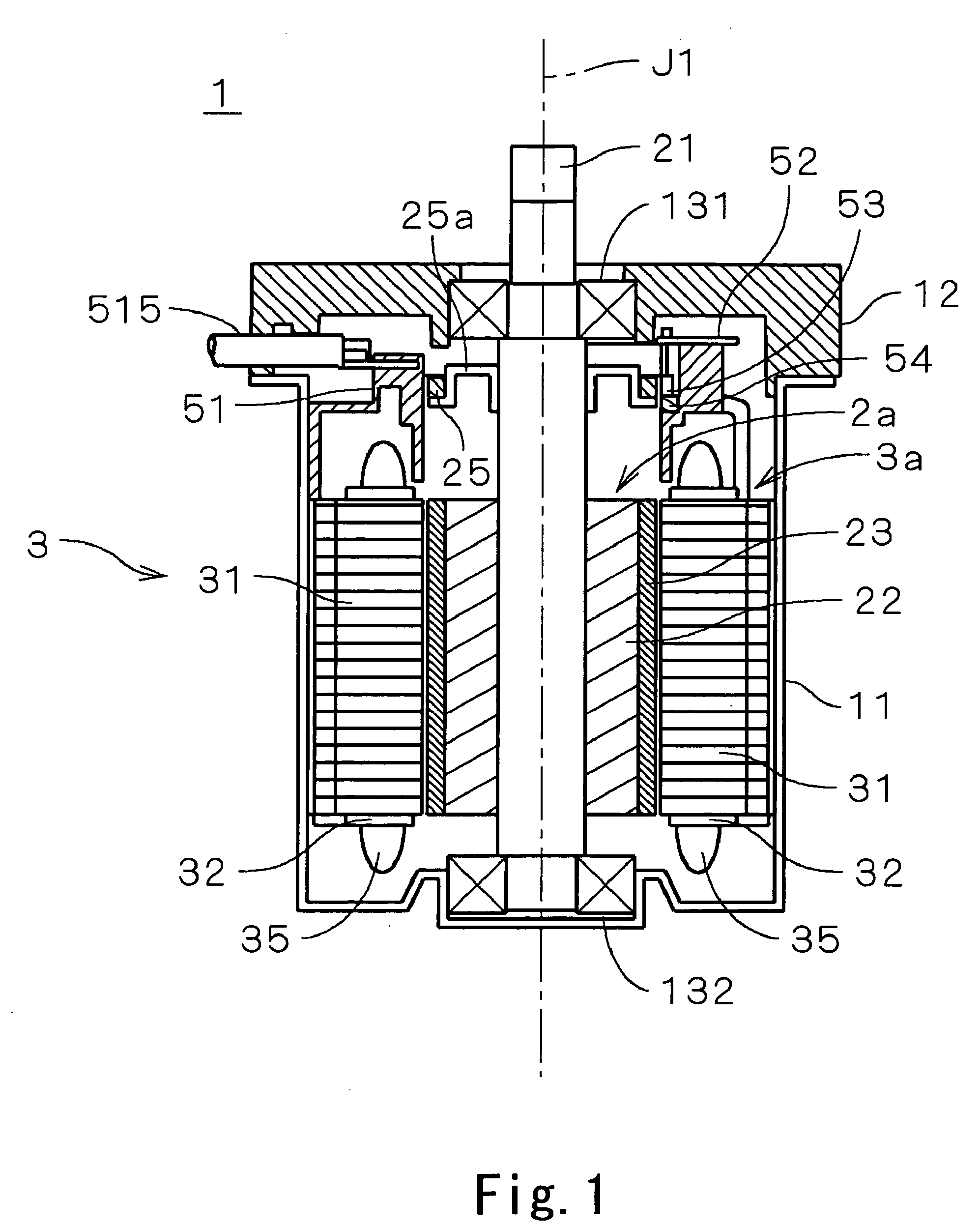
[0015] A motor 1 is a 3-phase brushless motor, which is used, for example, as a drive source for assisting for steering in an automobile power steering. In the meantime, representation of parallel oblique lines in a small sections of the section of FIG. 1 is omitted. The motor 1 is covered with a cylindrical housing 11 whose top is open in FIG. 1 and a cover portion 12 which closes the opening of the housing 11 and having an opening in its center.
[0016] Ball bearings 131, 132 are mounted on the opening of the cover portion 12 and on the bottom face of the housing 11 so that a shaft 21 is supported rotatably by those ball bearings 131, 132. A cylindrical rotor yoke 22 made of magnetic material is mounted on the shaft 21 within the housing 11 and a cylindrical field magnet 23 which is magnetized in multiple poles is fixed on the outer peripheral face of the rotor yoke 22.
[0017] On the other hand, a stator 3 is mounted on the inner peripheral face of the housing 11 such that it oppos...
second embodiment
[0032]FIG. 5 is a longitudinal sectional view of a motor 1a according to the second embodiment of the present invention. In the motor 1a, the hole sensor 53 is mounted on the circuit board 52 such that it opposes the main upper face perpendicular to the central axis J1 of the sensor magnet 25 (that is, disposed in the axial direction). The other structure of the motor 1a is substantially the same as that in FIG. 1 and like reference numerals are attached.
[0033] In the motor 1a, the sensor magnet 25 has magnetic field orientation parallel to the central axis J1 (axial anisotropy). The sensor magnet 25 is a neodymium-iron-boron base rare earth magnet manufactured according to the same method as the first embodiment and magnetized in multiple poles corresponding to the field magnet 23 around the central axis J1.
[0034] Because in the motor 1a, the hole sensor 53 can be mounted on the circuit board 52, the mounting of the hole sensor 53 onto the circuit board 52 is simplified. Further ...
third embodiment
[0036] The third embodiment is a modification of the first embodiment. In this embodiment, a second original member which is magnetized to be a field magnet is formed with a material different from that of the first original member, the second original member which is magnetized to be an isotropic rare earth magnet.
[0037] The isotropic field magnet generates rotational force with less cogging torque, while detection accuracy of the position of the field magnet is not deteriorated.
[0038] The embodiments of the present invention have been described above and the present invention is not restricted to the above embodiments but may be modified in various ways.
[0039] If considering that the motor of the above embodiment has high mechanical strength which inhibits itself from being damaged easily, is easily machined and relatively cheap, it is preferable to use neodymium-iron-boron base rare earth magnet as the sensor magnet 25. However, it is permissible to use other rare earth anisot...
PUM
 Abstract
Description
Claims
Application Information