Method and system for detecting an object using a composite evidence grid

a composite evidence and object technology, applied in the field of methods and systems for characterizing objects using composite evidence grids, can solve problems such as degrading the performance of laser range finders

Active Publication Date: 2006-06-15
DEERE & CO
View PDF15 Cites 64 Cited by
  • Summary
  • Abstract
  • Description
  • Claims
  • Application Information

AI Technical Summary

Problems solved by technology

However, the performance of the laser range finder may be degraded by precipitation, fog, rain, high humidity, or dust.

Method used


Image

  • Method and system for detecting an object using a composite evidence grid
  • Method and system for detecting an object using a composite evidence grid
  • Method and system for detecting an object using a composite evidence grid

Examples


Embodiment Construction

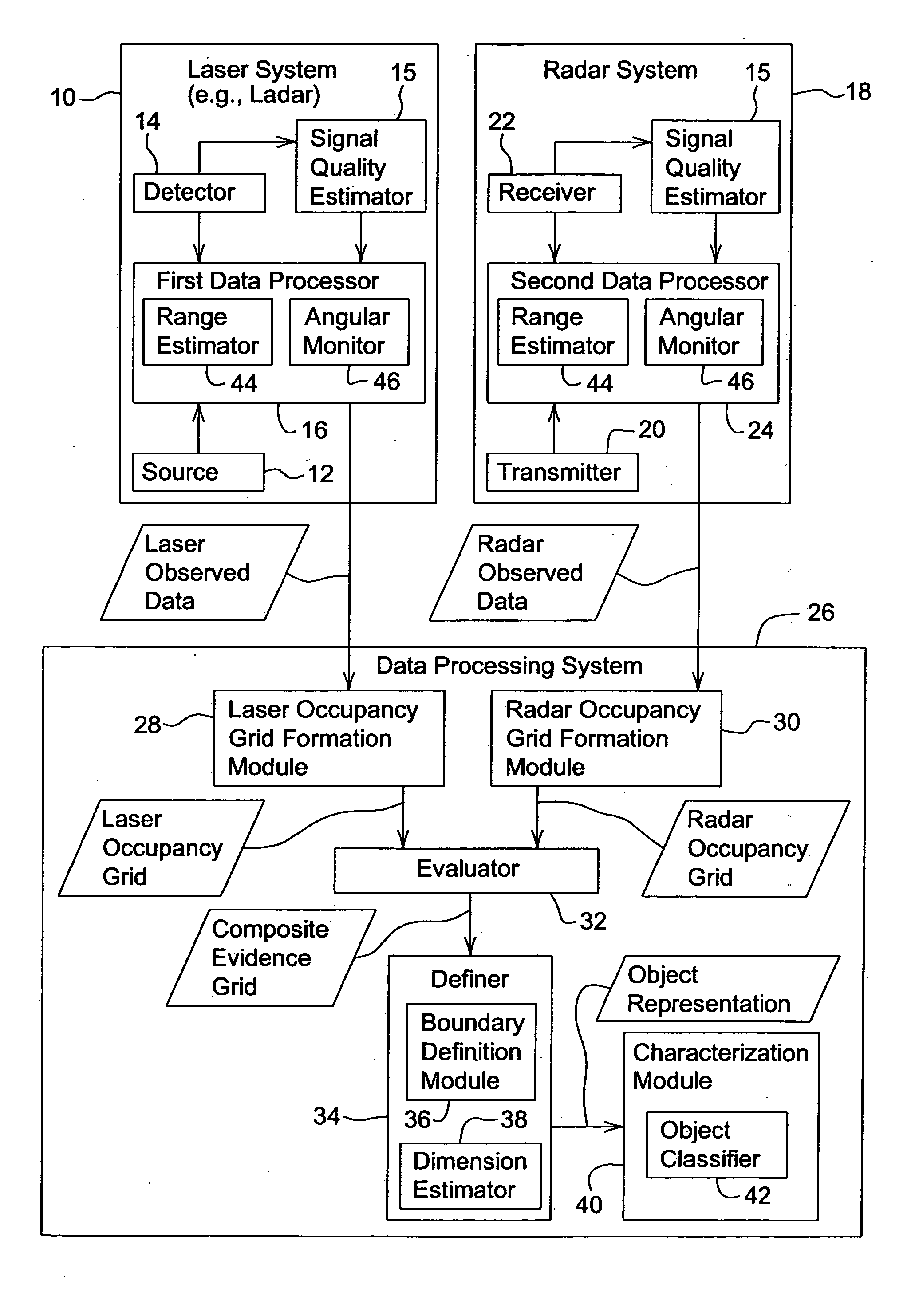
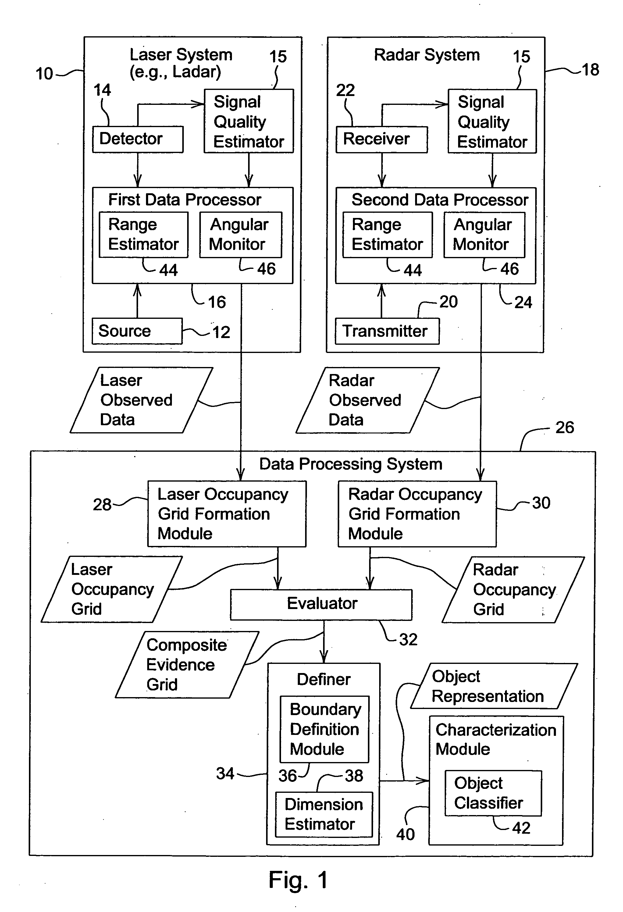
[0012] In accordance with FIG. 1, a laser system 10 and a radar system 18 are coupled to a data processing system 26. The laser system 10 (e.g., ladar or laser range finding system) comprises a source 12, a detector 14, a signal quality estimator 15, and a first data processor 16. The radar system 18 comprises a transmitter 20, a receiver 22, a signal quality estimator 15, and a second data processor 18. The data processing system 26 comprises a laser occupancy grid formation module 28, a radar occupancy grid formation module 30, an evaluator 32, a definer 34, and a characterization module 40.

[0013] In accordance with FIG. 1, a source 12 transmits a laser transmission in a first frequency range at a known angular orientation in a first zone. A detector 14 receives a reflection of the laser transmission from an object in the first zone to determine laser range data associated with points on the object for known angular orientation data. A transmitter 20 transmits a radar transmissio...


PUM


Abstract

A method and system for detecting an object uses a composite evidence grid based on dual frequency sensing. A source transmits a laser transmission in a first zone. A detector receives a reflection of the laser transmission from an object in the first zone to determine laser observed data associated with points on the object. A transmitter transmits a radar transmission in a second zone that overlaps with the first zone. A receiver receives a reflection of the radar transmission from an object in the second zone to determine radar observed data associated with points on the object. The laser observed data is processed to form a laser occupancy grid for the first zone and the radar observed data is processed to form a radar occupancy grid for the second zone. An evaluator evaluates the radar occupancy grid and the laser occupancy grid to produce a composite evidence grid for at least an overlapping region defined by the first zone and the second zone.

Description

FIELD OF THE INVENTION [0001] This invention relates to a method and system for characterizing an object using a composite evidence grid based on dual frequency sensing. BACKGROUND OF THE INVENTION [0002] In the prior art, a laser range finders have been used to determine representations of objects in a field of view. However, the performance of the laser range finder may be degraded by precipitation, fog, rain, high humidity, or dust. Thus, there is a need for enhancing the reliability and performance of the laser range finder in the presence of precipitation, fog, rain, high humidity, and dust. SUMMARY OF THE INVENTION [0003] In accordance with one embodiment of the method and system for detecting an object, a method and system for detecting an object uses a composite evidence grid based on dual frequency sensing. A source transmits a laser transmission over a first frequency range in a first zone. A detector receives a reflection of the laser transmission from an object in the fi...

Claims


Application Information

Patent Timeline
Patent Type & Authority Applications(United States)
IPC IPC(8): G01S13/42G01S13/931G01S17/86G01S17/931
CPCG01S7/41G01S7/4802G01S13/88G01S17/023G01S17/88G01S13/865G01S13/931G01S7/497G01S7/40G01S17/86G01S17/931
Inventor THACKRAY, ROBERT GEORGE
Owner DEERE & CO
Why Eureka
Try Eureka