Lens of variable focal length

a variable focal length, lens technology, applied in the field of lenses of variable focal length, can solve the problems of b>2/b> to rupture, unsatisfactory optical distortion,

Active Publication Date: 2006-06-15
INVENIOS FRANCE SAS
View PDF11 Cites 99 Cited by
  • Summary
  • Abstract
  • Description
  • Claims
  • Application Information

AI Technical Summary

Benefits of technology

[0006] One object of the present invention is to provide a lens of variable focal length that has optical properties which are not disturbed during assembly, storage and / or use of the lens by a variation in the pressure of the liquids contained within the lens.

Problems solved by technology

An excess of pressure of the liquids contained in the lens carries the risk of causing deformation of the upper and lower transparent plates 1, 2, resulting in undesirable optical distortion.
At worst, if the liquid pressure increase is too great, it may cause the transparent plates 1, 2 to rupture.

Method used


Image

  • Lens of variable focal length
  • Lens of variable focal length
  • Lens of variable focal length

Examples


Embodiment Construction

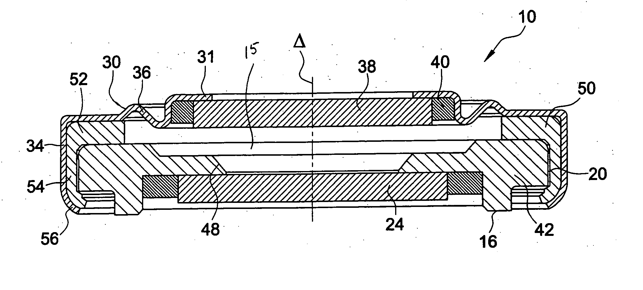
[0017] According to one embodiment of the invention, there is provided a structure of a lens with, an elastic element capable of deforming, preferably in response to variations in the pressure of the liquids contained in the lens, such that the deformation of the element has little or no influence on the optical properties of the lens. Thus, any deformation of parts which contribute to the optical properties of the lens is limited, thereby ensuring that the lens maintains its optical properties when the lens / lens mount is being assembled and when the lens is being used.

[0018]FIG. 2 depicts an exemplary embodiment of a mount for the lens of variable focal length according to the invention, at an intermediate step in the method of manufacturing the lens / mount assembly. The mount 10 for a lens of variable focal length according to the invention is made up of an upper part 12 and of a lower part 14 which are produced separately from one another and which, when assembled, define an inte...


PUM


Abstract

A lens assembly of variable focal length comprises two transparent plates (24, 38) at least partially facing each other and parallel to one another and delimiting, at least in part, an internal volume (15) containing two non-miscible liquids having different optical indices. The lens comprises an elastic element (36) capable of deforming in response to a change in pressure of the liquids, in such a way as to substantially maintain the optical properties of the lens assembly, e.g., in order to maintain the parallelism of the two transparent plates.

Description

CROSS-REFERENCE TO RELATED PATENT APPLICATIONS [0001] France Priority Application 04 / 52747, filed Nov. 24, 2004 including the specification, drawings, claims and abstract, is incorporated herein by reference in its entirety. FIELD OF THE INVENTION [0002] The present invention relates to lenses of variable focal length and more particularly to such lenses employing the deformation of a drop of liquid through electrowetting phenomena. BACKGROUND OF THE INVENTION [0003] Various embodiments of lenses of variable focal length are described in commonly owned European Patent No. 1,166,157. FIG. 1 of the current application is similar to FIG. 12 of that patent. A cell is defined by two transparent insulating plates 1 and 2 and side walls (not depicted). The lower plate 2, which is non-planar, comprises a conical or cylindrical depression or recess 3, of axis Δ, which contains a drop of an insulating liquid 4. The remainder of the cell is filled with an electrically conductive liquid 5, non-...

Claims


Application Information

Patent Timeline
Patent Type & Authority Applications(United States)
IPC IPC(8): G02B3/12
CPCG02B3/14G02B26/005G02B3/12
Inventor BERGE, BRUNOPESEUX, JEROMELAUNE, FREDERIC
Owner INVENIOS FRANCE SAS
Why Eureka
Try Eureka